


Rev. 1.01 Oct 28, 2008
(i)
REJ10J1351-0101
Table of Contents
Chapter1 Overview..............................................................................................................................1-1
1.1 Overview .................................................................................................................................................................... 1-2
1.2 Configuration.............................................................................................................................................................. 1-2
1.3 External Specifications ............................................................................................................................................... 1-3
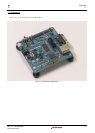
1.4 Appearance................................................................................................................................................................ 1-4
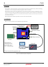
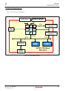
1.5 M3A-HS19 Block Diagrams........................................................................................................................................ 1-5
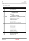
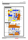
1.6 M3A-HS19 Board Overview ....................................................................................................................................... 1-6
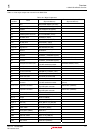
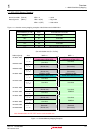
1.7 M3A-HS19 Memory Mapping ..................................................................................................................................... 1-9
1.8 Absolute Maximum Ratings...................................................................................................................................... 1-10
1.9 Recommended Operating Conditions ...................................................................................................................... 1-10
Chapter2 Features and Specifications.................................................................................................2-1
2.1 Features ..................................................................................................................................................................... 2-2
2.2 CPU............................................................................................................................................................................ 2-3
2.2.1 SH7619 ............................................................................................................................................................. 2-3
2.3 Memory ...................................................................................................................................................................... 2-4
2.3.1 SH7619 U Memory and Cache Memory ........................................................................................................... 2-4
2.3.2 Flash Memory S29GL032A90TFIR4 (Standard component)............................................................................. 2-4
2.3.3 External Synchronous DRAM (SDRAM) ........................................................................................................... 2-6
2.3.4 External EEPROM .......................................................................................................................................... 2-11
2.4 Serial Port Interface.................................................................................................................................................. 2-13
2.5 PCMCIA Card Interface............................................................................................................................................ 2-14
2.6 LAN Port Interface.................................................................................................................................................... 2-15
2.7 I/O Port..................................................................................................................................................................... 2-16
2.8 Power Supply Circuit................................................................................................................................................ 2-19
2.9 Clock Module............................................................................................................................................................ 2-20
2.10 Reset Module ......................................................................................................................................................... 2-21
2.11 Interrupt Switch ...................................................................................................................................................... 2-22
2.12 E10A-USB Interface ............................................................................................................................................... 2-23
Chapter3 Operational Specifications ...................................................................................................3-1
3.1 M3A-HS19 Connectors............................................................................................................................................... 3-2
3.1.1 UART Connector Pin (J1).................................................................................................................................. 3-3
3.1.2 UART Connector (J2)........................................................................................................................................ 3-4
3.1.3 RS-422 Connector Pin (J3) ............................................................................................................................... 3-5
3.1.4 PCMCIA Connector (J4).................................................................................................................................... 3-6
3.1.5 LAN Connector (J5) .......................................................................................................................................... 3-8
3.1.6 H-UDI Connector (J6) ....................................................................................................................................... 3-9
3.1.7 Power Supply Connector (J7) ......................................................................................................................... 3-10
3.1.8 External Power Supply Connector (J8) ........................................................................................................... 3-11
3.1.9 Expansion Connectors (J9-J13) .................................................................. 3-12
3.2 Switches and LEDs .................................................................................................................................................. 3-15
3.2.1 Jumpers (JP1 - JP9) ....................................................................................................................................... 3-16