


Operational Specifications
3.1.6 H-UDI Connector (J6)
Rev.1.01
Oct.28.2008 3-9
REJ10J1351-0101
3
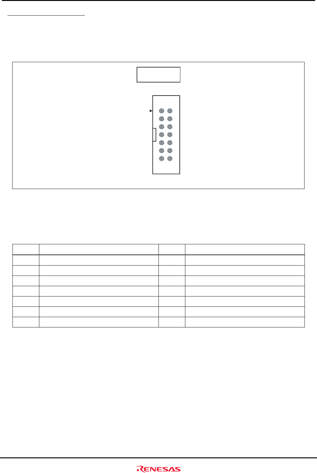
3.1.6 H-UDI Connector (J6)
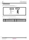
The M3A-HS19 is provided with an H-UDI (J6) connector to connect the E10A-USB emulator.
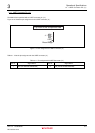
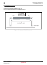
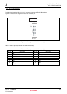
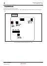
Figure 3.1.7 shows the pin assignment for the H-UDI connector (J6).
Top view the
component side
J6
1
7
H-UDI
8
14
Figure 3.1.7 Pin assignment for H-UDI Connector (J6)
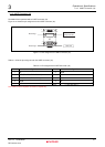
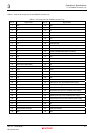
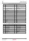
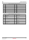
Table 3.1.6 lists the pin assignment for the H-UDI connector (J6).
Table 3.1.6 Pin assignment for H-UDI Connector (J6)
Pin no. Signal Name Pin no. Signal Name
1
TCK
8
N.C.
2
TRST#
9
(GND) ASEMD#
3
TDO
10
GND
4
N.C.
11
UVCC
5
TMS
12
GND
6
TDI
13
GND
7
RESET#
14
GND