


Features and Specifications
2.7 I/O Port
Rev.1.01
Oct 28, .2008 2-16
REJ10J1351-0101
2
2.7 I/O Port
Following I/O ports on the M3A-HS19 can be configured by the SH7619 MCU. These ports are multiplexed pins with up to
four features. Some pins have several initial features for normal mode and HIF (Host Interface) boot mode. Features can
be controlled by PFC (pin function controller).
• PA16 - PA25
• PB00 - PB13
• PC00 - PC20
• PD0 - PD7
• PE00 - PE24
The M3A-HS19 is connected with a memory, expansion connectors, a PCMCIA connector, a LAN connector, an RS-232C
connector, an RS-422 connector and other control ICs. Some I/O ports are connected to DIP switches and LEDs, which
can be used in the port mode as intended use. LED shows status in the PHY mode.
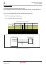
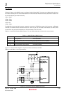
Table 2.7.1 lists Mode DIP Switch (SW4) Features. The state will be loaded when the board is reset and started.
Table 2.7.1 Mode DIP Switch (SW4) Features
SW4-No.
Description
1 ON: Big-endian OFF: Little-endian
2 ON: Host interface (HIF) is NOT operating OFF: Host interface (HIF) is operating
3 ON: Normal boot mode OFF: HIF boot mode
4 ON: Flash ROM is write-protected OFF: Write-enabled
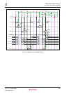
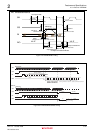
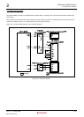
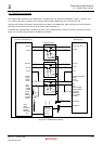
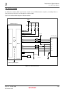
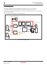
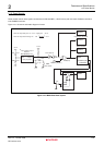
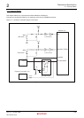
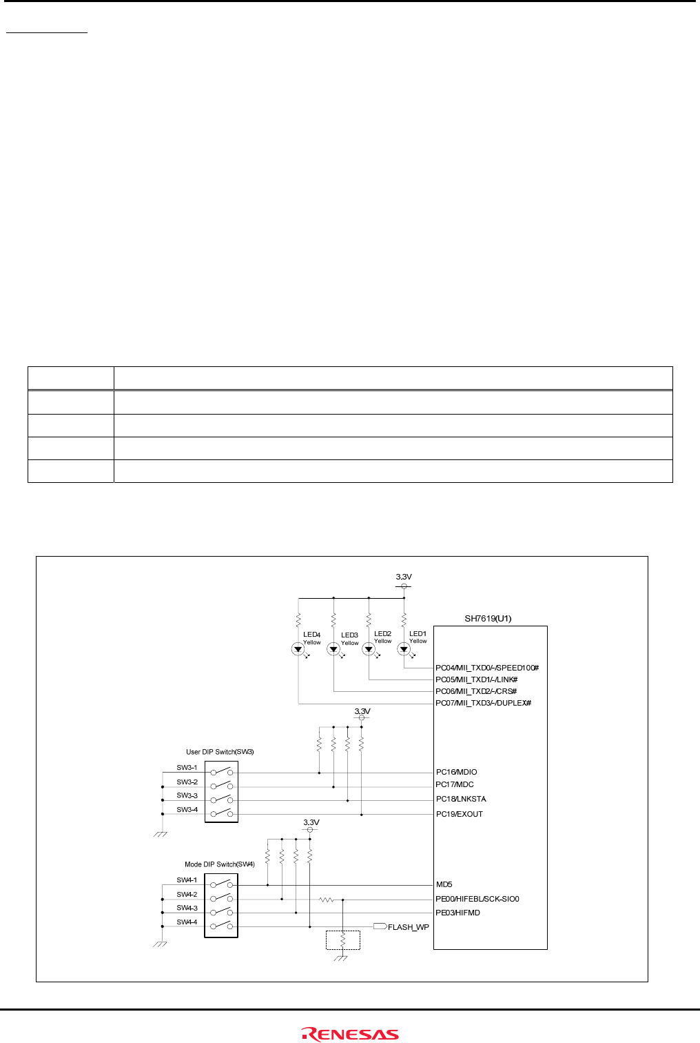
Figure 2.7.1 shows the block diagram of I/O port connections to switches and LEDs.
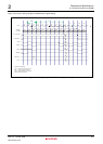
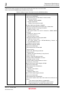
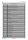
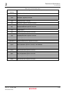
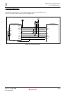
Table 2.7.2 and Table 2.7.3 list I/O port features.
Figure 2.7.1 I/O Port Connection to Switches and LEDs