


6.6. Option Links
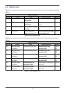
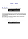
Table 6-5 below describes the function of the option links associated with Power configuration. The default configuration is indicated by
BOLD text.
Option Link Settings
Reference Function Fitted Alternative (Removed) Related To
R10 Power Source
Board can be powered from
PWR connector
Disable external power connector R44, R45
R37 Microcontroller Power Supply
Supply power to
Microcontroller
Fit Low ohm resistor to measure
current.
-
R44 Power Source Configuration
Connects external 5V supply
to the RSK.
Disconnects external 5V supply to the
RSK.
R10, R45
R45 Power Source Connects regulated 3.3V
voltage source to Board_VCC
Disconnects regulated 3.3V voltage
source from Board_VCC
R10, R44
Table 6-5: Power configuration links
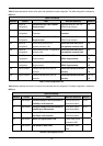
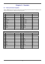
Table 6-6 below describes the function of the option links associated with Clock configuration. The default configuration is indicated by
BOLD text.
Option Link Settings
Reference Function Fitted Alternative (Removed) Related To
R42 Main clock Oscillator
Configuration
Connects external clock to MCU
Disconnects external clock
connection to MCU
R46, R47,
R52
R46 Main clock Oscillator
Configuration
Connects external clock to MCU
Disconnects external clock
connection to MCU
R42, R47,
R52
R47 Sub clock Oscillator
Configuration
Connects external clock to MCU
Disconnects external clock
connection to MCU
R42, R46,
R52
R52 Sub clock Oscillator
Configuration
Connects external clock to MCU
Disconnects external clock
connection to MCU
R42, R46,
R47
R48 Main clock Oscillator
Configuration
On board crystal (X1) is
connected to the CPU.
On board crystal (X1) is disconnected
from the CPU.
R42, R46
R53 Sub clock Oscillator
Configuration
On board crystal (X2) is
connected to the CPU.
On board crystal (X2) is disconnected
from the CPU.
R47, R52
Table 6-6: Clock configuration links
9