


Chapter 6. User Circuitry
6.1. Switches
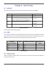
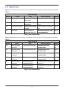
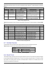
There are four switches located on the board. The function of each switch and its connection are shown in Table 6-1.
Switch Function Microcontroller
RES When pressed, the board microcontroller is reset. RESETn Pin9
SW1/BOOT* Connects to an IRQ input for user controls.
The switch is also used in conjunction with the RES switch to place
the device in BOOT mode when not using the E8A debugger.
INT0n Pin44
(Port 4, pin 5)
SW2* Connects to an IRQ Interrupt input line for user controls. INT1n Pin52
(Port 3, pin 6)
SW3* Connects to a Key In Interrupt input line for user controls INT2n Pin53
(Port 3, pin 2)
Table 6-1: Switch Functions
*Refer to schematic for detailed connectivity information.
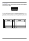
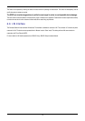
6.2. LEDs
There are six LEDs on the CPU board. The green ‘POWER’ LED lights when the board is powered. The orange BOOT LED indicates the
device is in BOOT mode when lit. The four user LEDs are connected to an IO port and will light when their corresponding port pin is set low.
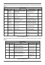
Table 6-2, below, shows the LED pin references and their corresponding microcontroller port pin connections.
LED Reference
(As shown on silkscreen)
Colour Microcontroller Port Pin function Microcontroller Pin
Number
LED0 Green Port 6.0 43
LED1 Orange Port 6.1 72
LED2 Red Port 6.2 71
LED3 Red Port 3.3 1
Table 6-2: LED Port
6.3. Potentiometer
A single turn potentiometer is connected to AN8 (P1.0) of the microcontroller. This may be used to vary the input analog voltage value to
this pin between VREF and Ground.
7