


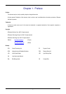
Chapter 5. Block Diagram
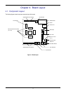
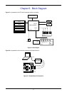
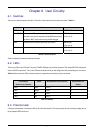
Figure 5-1 is representative of the CPU board components and their connectivity.
Boot mode pins
BOOT
Circuitry
D-type
Latch
RESET pin
RES
SW1
BOOT
SW2SW3
Switches
IRQ pins
POWER: Green
BOOT: Orange
LEDs
User LED x4
1Green, 1Orange, 2Red
I/OADC Input
Potentiometer
Application Board
Interface
Microcontroller Pin
Headers
E8
Serial Connector Option
Microcontroller
Power Jack Option
LCD Display
Data x4
Control x2
LIN Connector,
Power Connector for LIN
Figure 5-1: Block Diagram
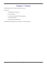
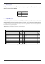
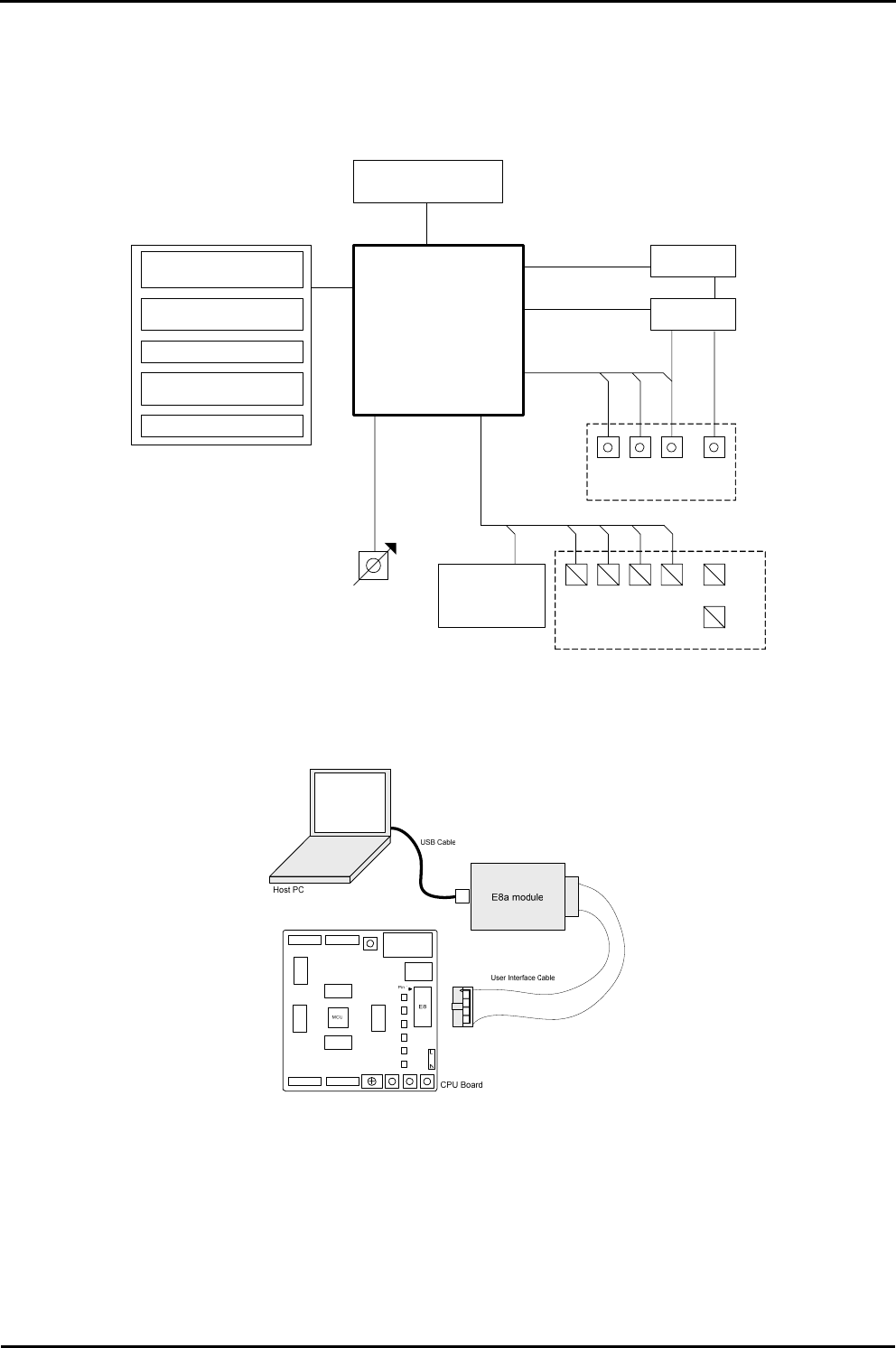
Figure 5-2 is representative of the connections required to the Renesas Starter Kit.
Figure 5-2 : Renesas Starter Kit Connections
6