


Chapter 9. Headers
9.1. Microcontroller Headers
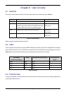
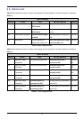
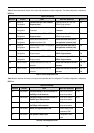
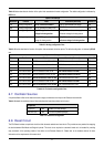
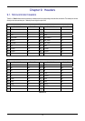
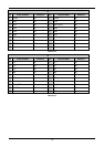
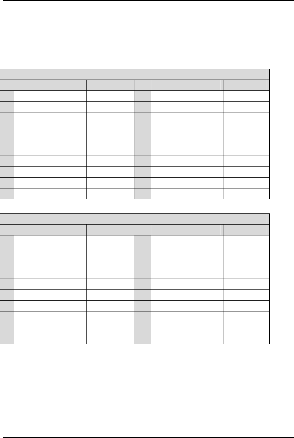
Table 9-1 to Table 9-4 show the microcontroller pin headers and their corresponding microcontroller connections. The header pins connect
directly to the microcontroller pins.
* Marked pins are subject to option links.
J1
Pin Circuit Net Name Device Pin Pin Circuit Net Name Device Pin
1 LED3 1 2 PIN2 2
3 PIN3 3 4 PIN4 4
5 PIN5 5 6 MODE 6
7 CON_XCIN 7 8 CON_XCOUT 8
9 RESETn 9 10 CON_XOUT 10
11 GROUND 11 12 CON_XOUT 12
13 VCC 12 14 PIN14 14
15 TRCIOC 14 16 TRCIOB 16
17 TRCIOA 16 18 TRCCLK 18
19 PIN19 18 20 PIN20 20
Table 9-1: J1
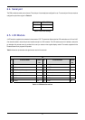
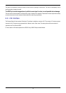
J2
Pin Circuit Net Name Device Pin Pin Circuit Net Name Device Pin
1 PIN21 21 2 PIN22 22
3 Wn 23 4 Vn 24
5 Wp 25 6 Vp 26
7 Un 27 8 TRIGb 28
9 Up 29 10 TRDCLK 30
11 TRIGa 31 12 CLK0 32
13 RXD0 33 14 TXD0 34
15 PIN35 35 16 TRISTn 36
17 DLCDE 37 18 DLCDRS 38
19 DLCD7 39 20 DLCD6 40
Table 9-2: J2
15