


Installation
26 Runco CL-810 Series Owner’s Operating Manual
PRE
L
IMINAR
Y
3.6
Connections to the
CL-810
Proceed as follows to connect the CL-810 to your video sources, external controller(s) -- if
present -- and AC power.
When connecting your equipment:
• Turn off all equipment before making any connections.
• Use the correct signal cables for each source.
• Ensure that the cables are securely connected. Tighten the thumbscrews on
connectors that have them.
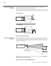
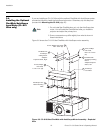
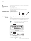
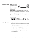
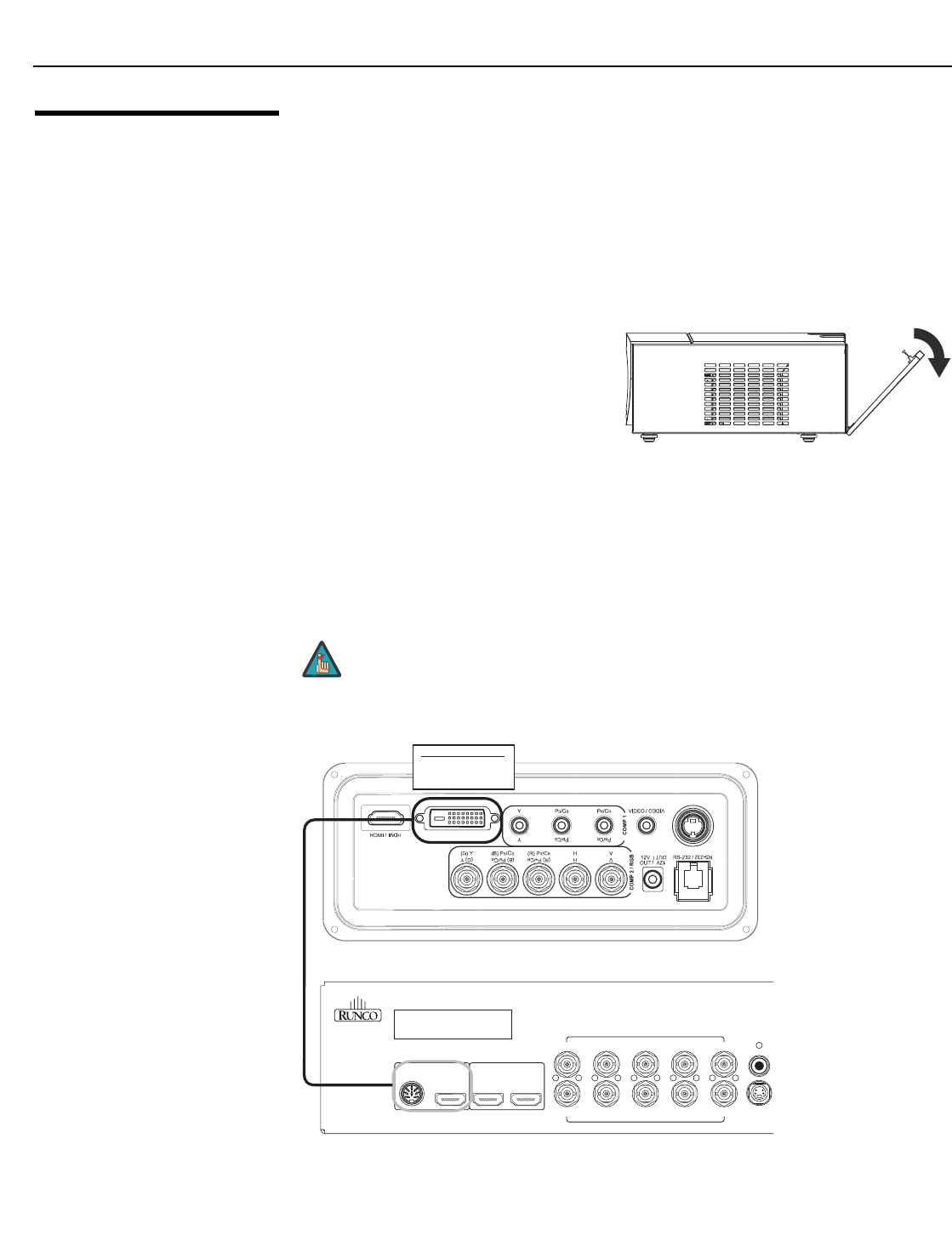
Connector Panel Access To access the connector panel, pull
firmly on the cable access cover to
open it.
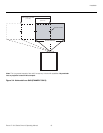
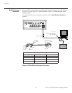
Connecting the SDC-1
System Expansion Device
to the CL-810
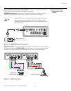
If (and ONLY if) your installation includes an SDC-1 System Expansion Device:
Use a Runco R-Link cable to connect the SDC-1 output to the CL-810 R-Link input; see
Figure 3-9.
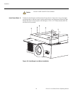
All signal sources should then be connected to the appropriate inputs on the rear panel of
the SDC-1. The signal from the SDC-1 is then output to the CL-810 projector via the
R-Link cable. For detailed instructions, refer to the SDC-1 Owner’s Operating Manual.
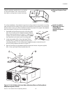
Figure 3-9. Connecting the CL-810 to the SDC-1
➤
➤
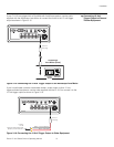
Connect ONLY an SDC-1 to the R-Link input! Although the
R-Link looks like a DVI input, it does not function like one and
cannot be used as an additional video input.
Note
S-VID /
S-VID
INPUT FROM SDC-1
INPUT FROM SDC-1
2
HDMI / DVI
1
VHBGR
VHBGR
HD-1 INPUTS
Runco International
Union City, CA
S-VIDEO
T
VIDEO
DIGITAL
INPUTS
HD-2 INPUTS
OUTPUTS TO
PROJECTOR
BOTH OUTPUTS MUST BE
CONNECTED TO PROJECTOR
Serial No
SDC-1
SYSTEM EXPANSION DEVICE
CL-810 Connector Panel
SDC-1 Rear Panel
R-LINK IN
(from SDC-1 Controller
R-Link Output to Projector
R-Link Input)