Controls and Functions
Runco LS-HB Installation/Operation Manual 5
PRE
L
IMINAR
Y
2.1
LS-HB at a Glance
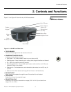
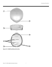
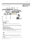
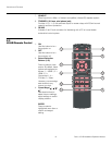
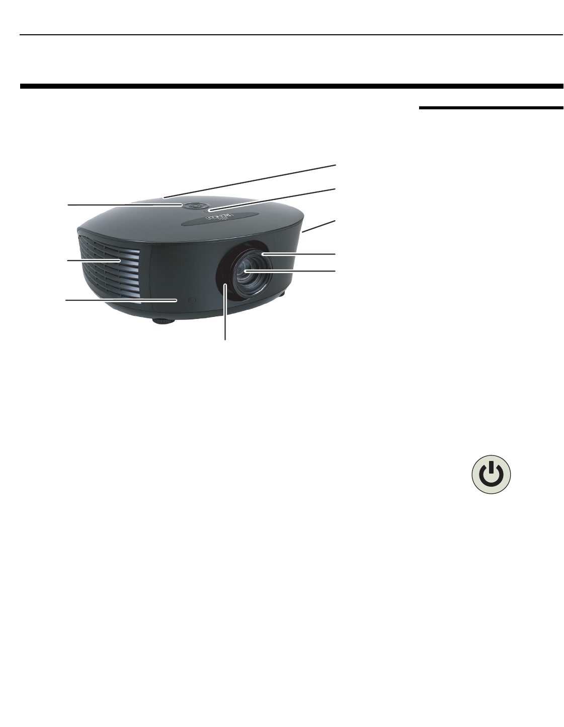
Figure 2-1 and Figure 2-2 show the key LS-HB components.
Figure 2-1. LS-HB Front/Side View
• TOP IR SENSOR
Receives infrared signals from the remote control unit.
• POWER BUTTON/STATUS LED
Indicates projector status as follows:
• Solid green = AC power present, ready to turn on (lamp not lit)
• Flashing green = lamp is warming up or cooling down; keypad functions not allowed
• Off = Lamp lit, projector functioning normally
• Alternating green/red = Lamp problem (door open, unable to strike, end of life), user
intervention likely to fix problem
• Flashing red = Over temperature, user intervention (clear vents, turn on AC) may fix
problem
• Solid red = Error that requires servicing (fan fail, Power-on self-test fail etc.)
• EXHAUST VENT
Warm air exits the projector through this vent. Ensure that it is not blocked.
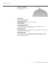
• FOCUS RING
Rotate this to focus the projected image.
• PROJECTION LENS
Available in two versions: standard throw range (1.89:1 to 2.40:1) and short throw
range (1.59:1 to 1.86:1).
2. Controls and Functions
System
Keypad
Intake
Vent
Front
IR Sensor
Top IR Sensor
Power Button/
Status LED
Exhaust Vent
(on side)
Focus Ring
Projection Lens
Zoom Ring


