


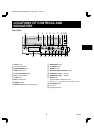
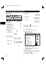
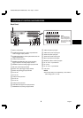
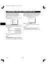
CONNECTIONS
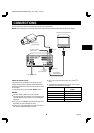
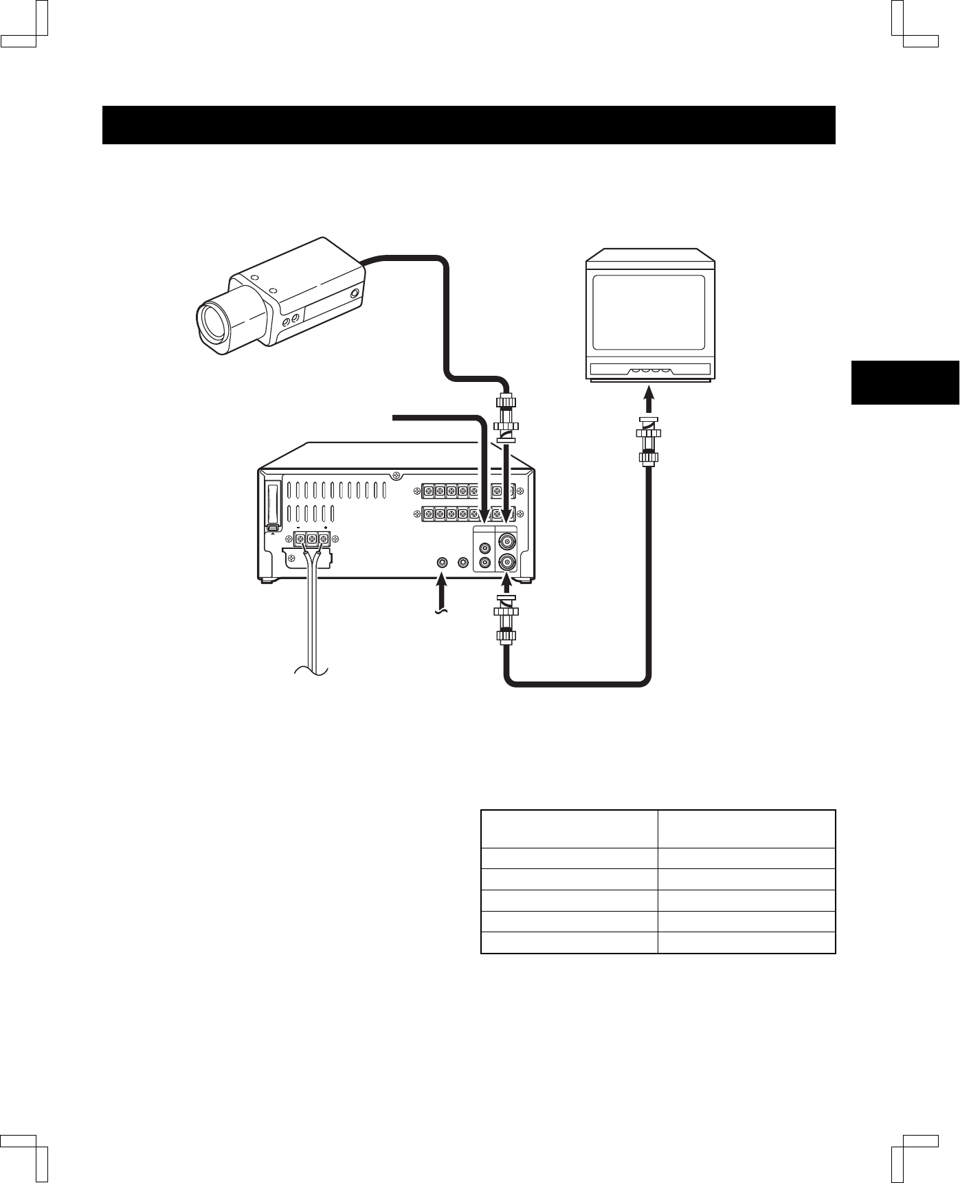
Connect the video camera and monitor TV as shown in the figure below.
NOTE:
Before making the connections, make sure all the devices are disconnected from the DC power supply.
ALARM IN/
CLOCK IN
COM
ALARM OUT/
CLOCK OUT
SERIES OUT/
NON REC OUT
SERIES
IN
OUT IN
EJECT
SW
OUT
TAPE
END OUT
COM
WARNING
OUT
COM
AUDIO VIDEO
OUT
OUT
IN
IN
MIC IN
REMOTE
PUSH
OPEN
Video camera
(sold separately)
Monitor TV (sold separately)
Coaxial cable
(sold separately)
To
VIDEO IN
jack
To
VIDEO OUT
jack
From an external
audio source
To remote
control
(sold separately)
DC12V IN
To DC power supply
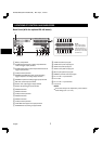
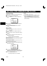
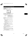
About the memory reset
If the VCR location is changed or to cancel previous
settings, please reset the memory as described below.
The time and date will be reset, and the security lock will
be cancelled.
To reset the memory, press the ALL RESET button.
NOTES:
•
For more details, please refer to the manuals
accompanying all other devices. If the connections are
not made properly, it may cause a fire or damage the
equipment.
•
You can use a VA-RMN01 Remote Control Unit (sold
separately) to control remotely the VCR.
•
If there is no video signal when the power is turned on,
“NO VIDEO” will be displayed on-screen.
•
Use a DC power cord rated A.W.G 18 (1.25 mm
2
) or
more.
•
The table below indicates the DC power source output
and DC power maximum cord lengths.
DC power source output DC power maximum cord
lengths
16 V 3 A 6 m
14 V 3.5 A 6 m
12 V 4.5 A 6 m
10 V 7 A 6 m
10 V 5 A 2 m
NU4QG/NA3 (SRT-2400DC GB) Mon. Sept., 17/2001
8
English