


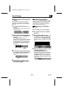
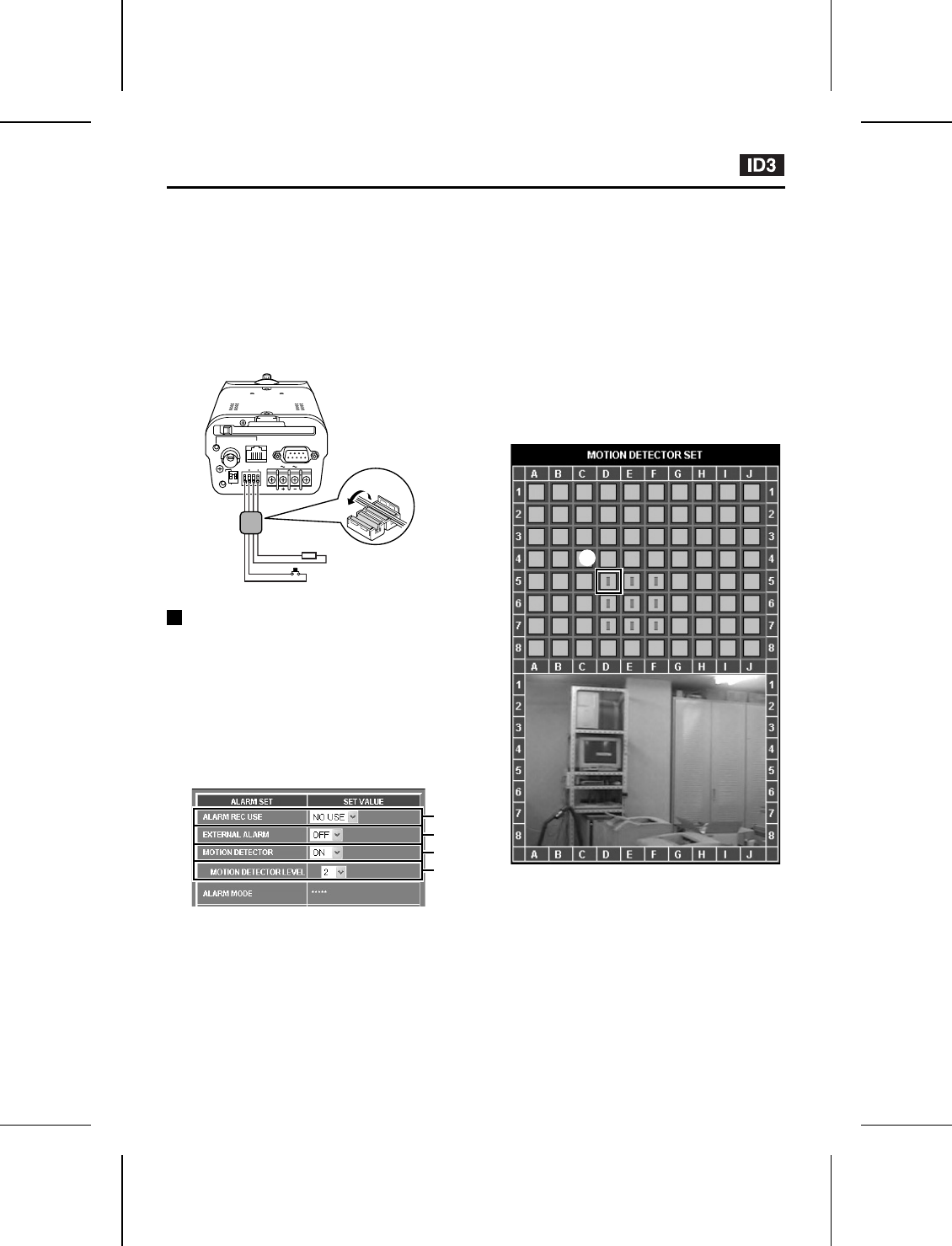
Alarm Settings
(Connection method)
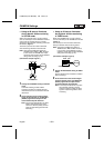
1
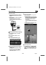
Connect an infrared sensor or similar to
the ALARM IN terminal at the rear of the
camera.
2
Connect a buzzer or lamp to the ALARM
OUT terminal.
Once the connections are complete,
install the supplied ferrite core (A) to the
power cord.
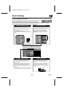
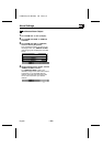
MOTION DETECTOR SET Settings
1
Set “ALARM REC USE” to “NO USE”
(example).
2
Set “EXTERNAL ALARM” to “OFF”
(example).
3
Set “MOTION DETECTOR” to “ON”.
The motion detector level and MOTION
DETECTOR SET screen will be displayed.
4
Use the drop-down list box to change the
“MOTION DETECTOR LEVEL” setting
(example: “2”).
The smaller the value selected, the higher
will be the sensitivity. Refer to “Motion
Detector Level Sensitivity Setting” for
further details. (p. 38)
5
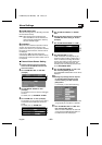
Set the sensor marks.
These correspond to the live image screen
and the sensing area.
1
Move the pointer to the same position
(grid area) as the area of the live image
screen that you would like sensing to
be carried out, and then click the
mouse button.
A sensor mark (ú) will be displayed. Click
in the same place once more to clear the
mark.
2
In the same way, insert sensor marks
in other places as required.
6
Click the [SET] button.
7
Set “ALARM OUT”, “ALARM OUT MODE”,
“ALARM OUT TIME”, “ALARM SOUND
MODE” and “ALARM BUFFERING” in the
same way as for “External Alarm Sensor
Setting”.
PC CARD
RS-232C
ALARM IN OUT
MODEM
PC
COMD/N IN
AC24V
DC12V
GND
1 2
ETHERNET
POWER
MONITOR
OUT
Infrared sensor or similar
Buzzer or lamp
A
CLASS 2 WIRING
1
2
3
4
1
L5AM2/US (VCC-WB4000) GB 2003, 6, 6
– 36 –
English