


side of the ribbon will be in contact with
the paper and the supply core is on the
rear spindle.
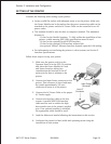
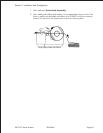
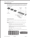
7. Slide the Ribbon Spindle Unit
over the Ribbon Drive
Spindles until the Head
Positioning Latch snaps into
position. The first position
corresponds to a 4.3" ribbon
width. If you are using a narrower
ribbon, press the Head Position
Latch while sliding the Ribbon
Spindle Unit to the correct
position. There are three latch
positions, one for a 4.3" wide
ribbon, one for a 3" wide ribbon
and one for a 1.75" wide ribbon.
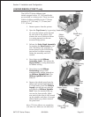
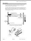
8. The ribbon should be center
justified (i.e., the center of the
ribbon roll should be aligned with
the center of the print head). If it
is not, reposition the Ribbon
Spindle Unit on the Drive
Spindles until the Ribbon
Position Latch is is in the
correct position.
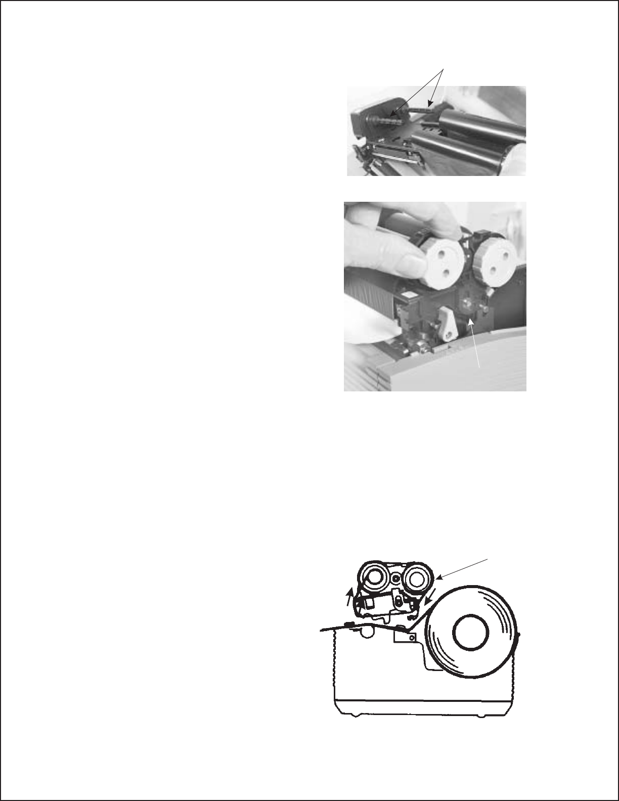
9. Route the ribbon leader under the print head and between the Ribbon
Assembly and the Paper Roller. Rotate the take-up spindle until the
leader is completely wound onto the take-up core.
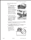
10. Push the Ribbon Assembly Latch to the up or locked position. Rotate
the Paper Roller upward and latch it by pushing the Ribbon
Assembly Latch into the upward position.
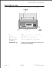
11. Latch the Print Head
Assembly in the closed
position by pushing
downward on the “PUSH”
tabs on both sides of the
assembly until it latches in
position.
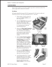
Ribbon Ass’y
Latch
Ribbon Drive
Spindles
Ribbon Path
Section 2. Installation and Configuration
Page 2-69001069A SATOCTSeriesPrinters