


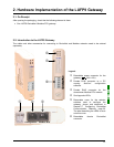

10
1. Introduction
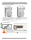
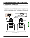
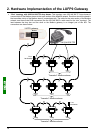
Each LUFP9 DeviceNet / Modbus RTU gateway allows a PLC on the DeviceNet network to command, control
and configure up to 8 Modbus slaves. If there are more than 8 Modbus slaves, you will need to use an
appropriate number of LUFP9 gateways. In the same way, if the exchanges with the Modbus slaves require
more than 25 Modbus commands (that is to say more than 50 queries and responses), you will have to distribute
the Modbus slaves over several gateways.
The LUFP9 gateway behaves both as a DeviceNet slave on the upstream network and as a Modbus RTU
master on the downstream network.
See chapter 7.2 Communication Characteristics, page 80, if you would like to read about the technical
communication characteristics of the LUFP9 gateway.
The gateway can carry out its data exchanges (inputs and outputs of all types) with the Modbus slaves cyclically,
aperiodically or in an event-driven way. All of these Modbus exchanges make up the gateway’s “Modbus
scanner” and we use the “ABC-LUFP Configurator” software application to configure this scanner’s exchanges.
Each item of data exchanged in this way is made available to the DeviceNet master, which can gain access to it
in a number of ways (cyclical, aperiodic or event-driven exchanges).
N.B. If, for example, a communication is periodic on the Modbus network, the corresponding data does not have
to be exchanged periodically on the DeviceNet network and vice versa.
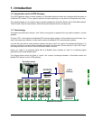
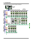
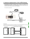
The diagram on the page to the left illustrates the distribution of several slaves over three downstream Modbus RTU
networks, each of these networks being interfaced with the DeviceNet master PLC using an LUFP9 gateway.
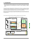
1.7. Principle Used to Configure and Operate the LUFP9 Gateway
The gateway is part of a family of products (referred to as LUFPz) designed to meet generic needs for
connection between two networks using different communication protocols.
The software elements common to all these gateways (a configuration tool known as “ABC-LUFP Configurator”
and the on-board Modbus software) cohabit with the specific features of the network upstream of each of them
(DeviceNet in the case of the LUFP9 gateway) generically. This is one of the reasons why the interfacing between
the upstream network and the Modbus network is carried out entirely via the gateway’s physical memory.
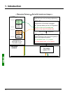
Ö The exchanges between the gateway (which operates as a Modbus master) and the Modbus slaves are
wholly configured using the “ABC-LUFP Configurator”. This configuration tool goes into great detail (setting
timers for exchanges, communication modes, frame content, etc.), which makes it all the more delicate to
use. So a whole chapter in this guide (chapter 6 Configuring the Gateway, page 40) has been devoted to this
tool.
By configuring the queries and responses for Modbus commands via this tool the user can create links
between a part of the content of the corresponding Modbus frames and the content of the gateway’s physical
memory (input memory for the content of the Modbus responses and output memory for the content of the
queries).
Ö The exchanges between the DeviceNet master PLC and the LUFP9 gateway should be configured in such a
way that the DeviceNet master can read the input data and write the output data from the gateway, but only
the data used for the Modbus exchanges (see previous point).