


86
9. Appendix C: Practical Example (RSLogix 500)
A practical example can be found on the CD LU9CD1. It is made up of two files. The first of these,
“
SLC_Guide_LUFP9.dnt”, shows the configuration of the DeviceNet scanner in RsNetWorx, described in the
previous chapters. The second, “
SLC_Guide_LUFP9_EN.rss”, is an RSLogix 500 file and so this is the
example itself.
As the configuration of the RsNetWorx file corresponds exactly to that shown in the previous chapters, we will
not be repeating its content here. On the other hand, the RSLogix 500 file is described below, based on the
structure of the sub-programs used.
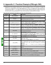
9.1. Main Program: “LAD 2 - MAIN_LUFP9”
The role of the main program is to activate the DeviceNet and Modbus communications, and to call the other
sub-programs, described in later chapters. The processes carried out in the main program are described below,
in the order in which they are run:
• Validation of the scanner’s DeviceNet exchanges by activation of bit O:1.0/0.
• Activation of the gateway’s Modbus communications using bits 13 (FB_DU) and 14 (FB_HS_SEND) of the
DeviceNet master’s command word (see chapter 5 Gateway Initialization and Diagnostics, page 33). These
two bits correspond to DeviceNet scanner bits O:1.1/5 and O:1.1/6.
N.B. This process is only relevant
provided that the “Control/Status Byte” option is set to “Enabled”. With the LUFP9 gateway’s default
configuration (“Control/Status Byte” = “Enabled but no startup lock”), this process is irrelevant but may still
be kept.
Finally, this example should not be used when this option is set to “Disabled”, because words I:1.1
and O:1.1 are no longer reserved for “managing the downstream Modbus network”. Please see chapter 5
Gateway Initialization and Diagnostics, page 33, for further information on this subject.
• Automatic acknowledgement of the gateway diagnostics by the DeviceNet master. All you have to do is
copy the value of bit 15 (ABC_HS_SEND) of the gateway’s status word to bit 15 (FB_HS_CONFIRM) of the
DeviceNet master’s command word (see chapter 5 Gateway Initialization and Diagnostics, page 33). This
automatic acknowledgement is mainly designed not to halt the mechanism for feeding diagnostics back
from the gateway to the DeviceNet master.
• Controlling/monitoring the “TeSys U n°1” motor starter by using sub-program U:3, that is to say the “LAD 3 -
CMD_SURV” sub-program. This sub-program uses local variables as parameters. The word N7:0 is used to
index both the output register and the input register used to control and monitor the “TeSys U n°1” motor
starter. So before calling the sub-program, the value of this word is set to 2 in order to access the words
O:1.2 and I:1.2. N7:0 is also used to index one of the bits of each of the registers N7:32, 33, 34 and 35
(registers handled by the user).
• Controlling/monitoring motor starter “TeSys U n°2”: Ditto, but setting the value of N7:0 to 3 (O:1.3 and I:1.3).
• Controlling/monitoring motor starter “TeSys U n°3”: Ditto, but setting the value of N7:0 to 4 (O:1.4 and I:1.4).
• Controlling/monitoring motor starter “TeSys U n°4”: Ditto, but setting the value of N7:0 to 5 (O:1.5 and I:1.5).
• Controlling/monitoring motor starter “TeSys U n°5”: Ditto, but setting the value of N7:0 to 6 (O:1.6 and I:1.6).
• Controlling/monitoring motor starter “TeSys U n°6”: Ditto, but setting the value of N7:0 to 7 (O:1.7 and I:1.7).
• Controlling/monitoring motor starter “TeSys U n°7”: Ditto, but setting the value of N7:0 to 8 (O:1.8 and I:1.8).
• Controlling/monitoring motor starter “TeSys U n°8”: Ditto, but setting the value of N7:0 to 9 (O:1.9 and I:1.9).
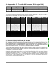
• Reading the value of a single parameter out of all of the TeSys U motor starters, by using the U:4 sub-
program, that is to say the “LAD 4 - LECT_PAR” sub-program.
• Writing the value of a parameter in a single TeSys U motor starter at a time, by using the U:5 sub-program,
that is to say the “LAD 5 - LECT_PAR” sub-program.
• Updating output 0:1.16 using the two counters N7:36 and N7:37. This output corresponds to the two
“Trigger bytes” that trigger the emission of both the parameter reading request (LSB) and the parameter
writing request (MSB). These two counters are independantly updated in the following sub-programs: “LAD
4 – RD_PAR”, for N7:36, and “LAD 5 – WR_PAR”, for N7:37.
N.B. You can read a parameter on all the motor starters and write a parameter on one of them at the same time
as these services use different Modbus commands.