


53
6. Configuring the Gateway
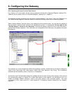
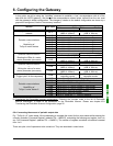
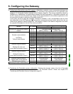
In this guide, we will be using the “AutoMap” command to establish a “raw” correspondence with all of the
data from the LUFP9 gateway. We then get the correspondence shown below, derived from the one used
with the gateway’s default configuration. The changes in relation to the default configuration are shown by a
greyed-out background, like the “free memory locations”.
Description
Service PLC input
Bit 0
......................Bit 7 Bit 8 ...................Bit 15
LUFP9 gateway status word
Managing the downstream Modbus
network
I:1.1
(MSB Æ 16#xx••) (LSB Æ 16#••xx)
I:1.2
Value of the motor starter c status register
I:1.3
Free memory location
I:1.4
Value of the motor starter e status register
I:1.5
Value of the motor starter f status register
I:1.6
Value of the motor starter g status register
I:1.7
Value of the motor starter h status register
I:1.8
Value of the motor starter i status register
Periodic communications
—
Monitoring of
TeSys U motor starters
I:1.9
Value of the motor starter j status register
I:1.10
Free memory location Slave no. (16#01-16#08)
I:1.11
Function number (16#03) Number of bytes read (16#02)
Value of the parameter read
Aperiodic communications
—
Reading the value of a motor
starter parameter (
RESPONSE)
I:1.12
(MSB Æ 16#xx••) (LSB Æ 16#••xx)
I:1.13
Slave no. (16#01-16#08) Function no. (16#06)
Address of the parameter written
I:1.14
(MSB Æ 16#xx••) (LSB Æ 16#••xx)
Value of the parameter written
Aperiodic communications
—
Writing the value of a motor
starter parameter (
RESPONSE)
I:1.15
(MSB Æ 16#xx••) (LSB Æ 16#••xx)
Aperiodic communications
(“Trigger bytes” for the responses)
I:1.16
Read parameter
response counter
Write parameter
response counter
I:1.17
Value of the “TeSys U Status Register”
I:1.18
Value of the “Complementary Status Register”
I:1.19
Value of the “K7 Status Register”
I:1.20
Value of the “K7 Status Register 2 (free format)”
I:1.21
Value of the “K7 Status Register 3 (free format)”
I:1.22
Value of the “Warning Number” register
I:1.23
Value of the “Warning Register”
Periodic communications
—
Monitoring of
TeSys U motor starter d
I:1.24
Value of “Reserved : 2
nd
Warning Register”
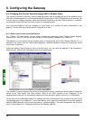
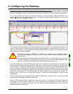
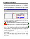
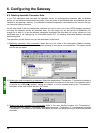
9) Transferring the DeviceNet scanner configuration: Following the changes made to the list of DeviceNet
scanner exchanges, it needs to be transferred to the DeviceNet scanner. Please see chapter 4.2.9
Transferring the DeviceNet Scanner Configuration, page 32.
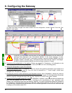
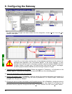
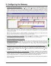
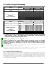
6.8.4. Increasing the amount of periodic output data
E.g. “TeSys U n°4” motor starter. We are attempting to complete the control for this motor starter whilst retaining the
currently controlled “Command Register” (address 704 = 16#02C0), and adding the following next register, that is to
say “2st Command Register” (address 705 = 16#02C1). The number of registers controlled is therefore increased
from 1 to 2.
There are quite a lot of operations to be carried out. They are described in order below: