


39
5. Gateway Initialization and Diagnostics
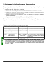
Due to the inversion of the LSB and the MSB for this register between the gateway and the DeviceNet master,
the structure of the corresponding output word (“O:1.1” in the case of the default configuration) is as follows:
Bits Description
8-15 Reserved.
7
FB_HS_CONFIRM: Acknowledgement bit of a gateway diagnostic
0-6 Reserved.
E.g. If the O:1.1 output word is set to 16#0080, the DeviceNet master command word will be set to 16#8000.
5.3. Simplified Operation
The two 16-bit registers located at addresses 16#0000-16#0001 (inputs) and 16#0200-16#0201 (outputs) are no
longer used for “managing the downstream Modbus network”. These two registers are no longer reserved and
so these addresses can be used to exchange data with the Modbus slaves (“Data Location” attribute of “Data” or
“Preset Data” type frame fields).
The DeviceNet master’s command word and the gateway’s status word, which we will be talking about in the rest
of this document, do not exist anymore. So the two warnings on pages 51 and 55 should be ignored, and the
input and output ranges in the gateway’s memory therefore go respectively from 16#0002-16#01FF to 16#0000-
16#01FF and from 16#0202-16#03FF to 16#0200-16#03FF.
If the gateway’s default configuration were to be configured in this way, it would clear DeviceNet scanner input
“I:1.1” and output “O:1.1”. These two words would then become “free memory locations”.