


57
6. Configuring the Gateway
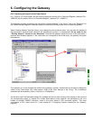
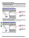
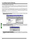
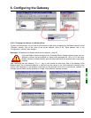
8) Configuring the DeviceNet master PLC outputs: In RsNetWorx, establish a new correspondence between the
data transmitted to the gateway and the PLC outputs, according to the requirements of your application (see
chapter 4.2.7 Configuring Outputs Intended for the Gateway, page 30). The various possibilities offered by
RsNetWorx for establishing a correspondence between the data transmitted to a DeviceNet subscriber and
the PLC outputs will not be covered here. Please see the documentation for this software application to find
out more about this step in setting up a DeviceNet master PLC.
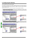
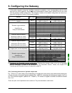
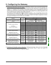
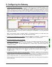
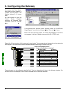
In this guide, we will be using the “AutoMap” command to establish a “raw” correspondence with all of the
data transmitted to the LUFP9 gateway. We then get the correspondence shown below, derived from the one
used with the gateway’s default configuration. The changes in relation to the default configuration are shown
by a greyed-out background, like the “free memory locations”.
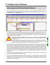
Description
Service PLC output
Bit 0
......................Bit 7 Bit 8 ...................Bit 15
DeviceNet master command word
Managing the downstream Modbus
network
O:1.1
(MSB Æ 16#xx••) (LSB Æ 16#••xx)
O:1.2
Value of the motor starter c command register
O:1.3
Value of the motor starter d command register
O:1.4
Value of the motor starter e command register
O:1.5
Free memory location
O:1.6
Value of the motor starter g command register
O:1.7
Value of the motor starter h command register
O:1.8
Value of the motor starter i command register
Periodic communications
—
Controlling
TeSys U motor starters
O:1.9
Value of the motor starter j command register
O:1.10
Slave no. (16#01-16#08) Function no. (16#03)
Address of the parameter to be read
O:1.11
(MSB Æ 16#xx••) (LSB Æ 16#••xx)
Number of parameters to be read
Aperiodic communications
—
Reading the value of a
motor starter parameter (Q
UERY)
O:1.12
(MSB Æ 16#00••) (LSB Æ 16#••01)
O:1.13
Slave no. (16#01-16#08) Function no. (16#06)
Address of the parameter to be written
O:1.14
(MSB Æ 16#xx••) (LSB Æ 16#••xx)
Value of the parameter to be written
Aperiodic communications
—
Writing the value of a
motor starter parameter (Q
UERY)
O:1.15
(MSB Æ 16#xx••) (LSB Æ 16#••xx)
Aperiodic communications
(“Trigger bytes” for the queries)
O:1.16
Read parameter
query counter
Write parameter
query counter
O:1.17
Value of the “Command Register”
Periodic communications
Monitoring of TeSys U motor starter f
O:1.18
Value of the “2nd Command Register”
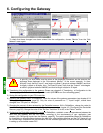
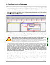
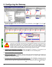
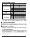
9) Transferring the DeviceNet scanner configuration: Following the changes made to the list of DeviceNet
scanner exchanges, it needs to be transferred to the DeviceNet scanner. Please see chapter 4.2.9
Transferring the DeviceNet Scanner Configuration, page 32.