


69
6. Configuring the Gateway
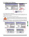
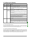
6.11.2.3. Configuring the Response
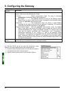
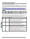
Next select the “Response” element from the Modbus command.
The various elements of the configuration of the response for this
command are shown opposite. The values displayed correspond to
the default values for any new command.
These elements allow you to configure a single aspect of managing the command, described at the top of the
page on the right. Each of these elements is described, in order, in the table below.
Configuration
element
Description
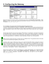
Trigger byte
This element is used by the gateway to activate the unitary incrementation of an 8-bit
counter in order to notify the DeviceNet master of the receipt of a new response to the
associated Modbus command. It takes one of the following two values:
- Disabled.................................. Default configuration. The gateway does not increment any
counter on receipt of the Modbus response.
- Enabled .................................. Each time that the gateway receives a new response to the
associated Modbus command, it increments the value of an 8-bit counter designated
by the “Trigger byte address” element (see below). If used, this counter allows the
DeviceNet master, for example, to only consider the response’s corresponding data
when this counter’s value is incremented.
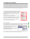
Trigger byte
address
This element is only used by the gateway if the element “Trigger byte” is set to “Enabled”. In
this case, it specifies the address, in the gateway’s input memory (16#0002 to 16#0002), of
an 8-bit counter managed by the gateway.
When the gateway receives a response to the associated Modbus command, it increments
the value of this counter in a unitary manner (value = value+1). So the DeviceNet master
must have access to this counter in the same way as for the periodic input registers from
the TeSys U motor starters.
This mode allows the DeviceNet master to be informed that a new response is available.
This can be useful, for example, if it is possible that the data from two consecutive
responses may be identical.
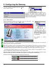
N.B.: In the specific case of the gateway’s default configuration, the “Trigger byte” element
for responses to the “Transactions 1” and “Transactions 2” personalized commands of the
“TeSys U n°1” node is set to “Enabled”. Hence, the management of responses to read and
write commands for parameters is
event driven.
The “Trigger byte address” elements of the “Response” elements for these two commands
are configured at addresses 16#001E and 16#001F. These are the “parameter read/write
response counters”. Considered under DeviceNet and RSNetWorx, these two data are
configured the same way as the other inputs (see chapter 4.2.6Configuring Inputs from the
Gateway, page 29) and both correspond to the I:1.16 input.
The DeviceNet master PLC will be able to detect the receipt of a response from a Modbus
slave by comparing the previous value and the current value of the associated counter
(address 16#001E or 16#001F). If there is a
unitary incrementation of this counter, the PLC
may, for example, read all of the data from the response (addresses 16#0013 to 16#0017
or addresses 16#0018 to 16#001D) and allow the transmission of a new query for reading
or writing the value of a parameter (using a “Trigger byte” for the queries). Contrarily to the
counter one can associate to the queries of any command, a response’s “Trigger byte” is a
true modulo 256 counter,
i.e. zero must be managed (… 254, 255, 0, 1, 2 …).
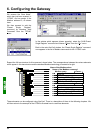
E.g. With the ATS48, we do not want the response to be event driven. So we will be retaining the default
configuration.