


19
2. Hardware Implementation of the LUFP9 Gateway
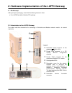
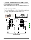
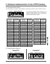
2) Cables:
VW3 A8 306 R•• Modbus cable ...................................
(“star” topology / “bus” topology with tap boxes)
Shielded cable with a male RJ45 connector at each
end.
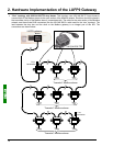
VW3 A68 306 Modbus cable........................................
(“bus” topology with tap boxes)
Shielded cable with a male RJ45 connector and a
male 15-point SUB-D connector. It is used to connect
a Modbus subscriber (slave or master) to a
TSXSCA62 or TSXCA50 box.
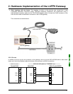
Shielded double twisted pair Modbus cable.................
(“bus” topology with branch boxes)
Bare cable (without connectors) used to make up the
main section of the Modbus network. There are three
items available: TSXCSA100 (100 m), TSXCSA200
(200 m), and TSXCSA500 (500 m).
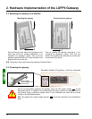
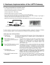
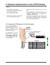
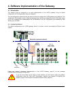
2.6. Connecting the LUFP9 gateway to the DeviceNet network
If the LUFP9 gateway is
physically located either end of
the DeviceNet network, you will
need to connect a line
termination to the terminals on
its DeviceNet connector.
The resistance of this line
termination should be equal to
121 Ω and it should be
connected between pins 2 and 4
on the gateway connector, that
is to say between the CAN_L
and CAN_H signals.
DeviceNet cable
Pin Name Wire colour
1GNDBlack
2 CAN_L Blue
3 SHIELD None (bare wire)
4CAN_HWhite
5V+Red
Detachable female
connector
Pinouts
Modbus
LUFP9
Gateway