


UX-258TH
FO-475TH
3-5. Documents requiring use of document carrier
1) Documents smaller than B6 (128mm x 182mm).
2) Documents thinner than the thickness of 0.06mm.
3) Documents containing creases, folds, or curls, especially those whose
surface is curled (maximum allowable curl is 5mm).
4) Documents containing tears.
5) Carbon-backed documents. (Insert a white sheet of paper between
the carbon back and the document carrier to avoid transfer of carbon
to the carrier.)
6) Documents containing an easily separable writing material (e.g., those
written with a lead pencil).
7) Transparent documents.
8) Folded or glued documents.
Document in document carrier should be inserted manually into the
feeder.
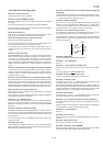
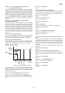
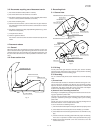
4. Document release
4-1. General
When the release lever is pulled by hand in the direction of arrow, the
latch is released and the upper document guide moves on its axis in the
derection of the arrow. The feed rollers, the separation rubber plate, and
the pinch rollers become free to make it possible to remove the docu-
ment.
4-2. Cross section view
Fig. 5
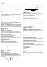
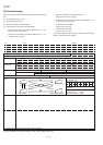
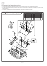
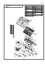
5. Recording block
5-1. General view
3 – 2
Operation panel unit
Scanner frame unit
PWB case unit
Lower cabinet
Fig. 6
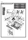
5-2. Driving
Via the pulse motor gear shaft, the reduction gear, and the recording
paper feed gear, rotation of the pulse motor is conveyed to the recording
paper feed roller to feed the recording paper.
5-3. Recording
Use of a thermal head permits easier maintenance and low operating
costs.
1) Thermal head
The thermal head consists of 1728-dot heat elements arranged in a sin-
gle row and has the resolution of 8 dots/mm. The maximum recording
speed is 10ms/line. The thermal head also incorporates a 1728-dot shift
register latch and output control driver circuit. Low power consumption
is achieved by dividing the head into nine segments.
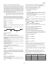
2) Structure of the recording mechanism
Recording is accomplished by pressing the thermal head on the record-
ing paper against the platen roller.
The main scan (horizontal) is electronically achieved, while the subscan
(vertical) is achieved by moving the recording paper by the recording
platen roller.
Usually, the cause for uneven print tone is caused by misalignment of
the thermal head or uneven contact with the roller.
It can be checked in the following manner.
1) Check if the thermal head power and signal cables are properly routed.
2) Check that the thermal head pivot moves smoothly up and down.
3) Check that the thermal head support bracket is secured without any
play.
4) Check to see that the recording platen roller has proper concentricity,
in the case of a print tone variation evenly repeated down the page.
5) Replace the thermal head with a new one and check to see if the
same trouble occurs.
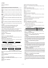
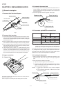
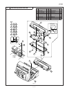
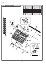
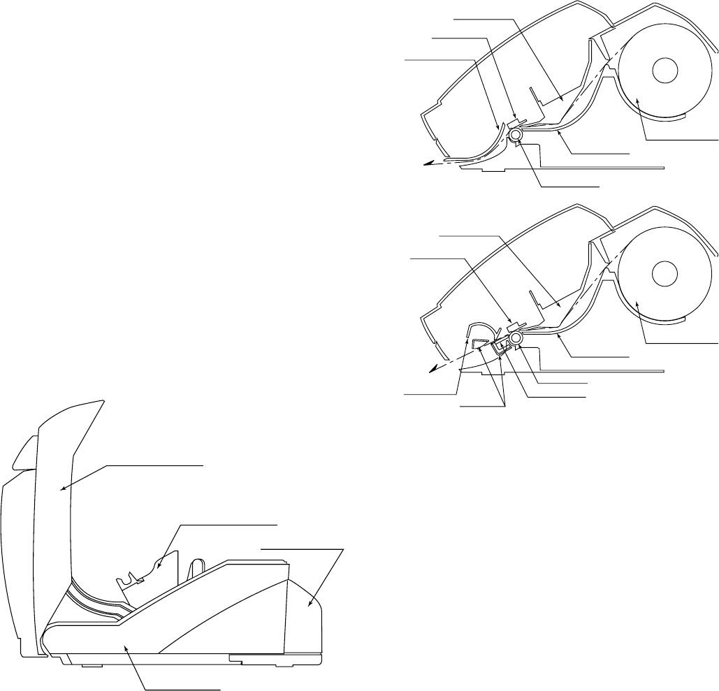
RECORDING BLOCK (CUTTER MODEL)
Scanner frame
Thermal head
Cutter cover
Platen roller
Paper support
Recording paper
Cutter guide
Cutter unit
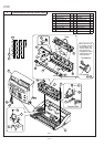
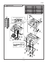
RECORDING BLOCK (NON CUTTER MODEL)
Scanner frame
Thermal head
Paper guide upper
Platen roller
Paper support
Recording paper