


UX-258TH
FO-475TH
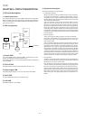
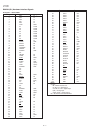
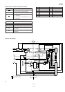
Signal Name Description
CML
Line connecting relay and DP generating relay
(The circuit is located H: Line make
in the TEL/LIU PWB.) L: Line break
SP MUTE
Speaker tone mute control signal
(The circuit is located H: Muting (Power down mode)
in the TEL/LIU PWB.) L: Muting cancel (Normal operation)
Handset reception mute control signal
TEL MUTE H: Muting
L: Muting cancel
Speaker volume control signal,
VOL A VOL B VOL C matrix
VOL A
VOL B
VOL C
(The circuit is located
in the control PWB.)
TXCONT
TXOUT mute signal
(The circuit is located
L: Signal sending, when transmitting
in the control PWB.)
H: During reception, transmission mute,
(during standby)
GAIN-C
Reception gain switching signal
(The circuit is located H: When connected to line, 1: 1 gain
in the control PWB.) L: When not connected to line, HIGH gain
BZCONT
Speaker output signal switching
(The circuit is located H: Buzzer signal output
in the control PWB.) L: When monitoring line signal
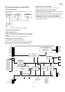
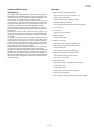
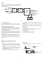
5. Externally connected TEL OFF HOOK detection circuit section
• The circuit current detection is turned on together with OFF HOOK
of main body or OFF HOOK of externally connected TEL. ON of
CML OFF is judged as OFF HOOK of externally connected TEL.
6. CI detection circuit
• CI is detected by the photocoupler which is integrated in series in
the primary side TEL circuit well proven in the existing unit.
7. Signal/DTMF transmission level & receiving level
• Signal transmission level setting: ATT 7 dB Circuit output: 7 dBm.
• DTMF transmission level setting: HF -6.0 dBm LF -7.0 dBm
Thus, set the level.
• Attenuation in the LIU section of the receiving level is degigned at
-6 dBm. (The modem and circuit error are not included.)
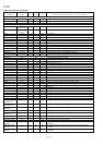
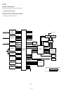
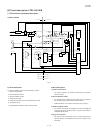
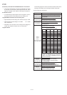
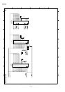
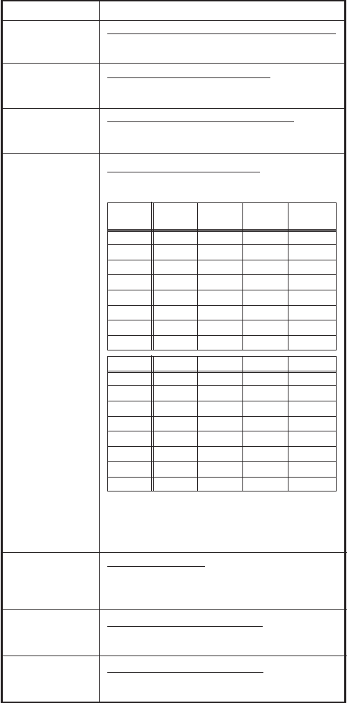
7. Signal selection
The following signals are used to control the transmission line of TEL/
FAX signal. For details, refer to the signal selector matrix table.
[Control signals from output port]
5 – 9
OUTPUT VOL A VOL B VOL C
OH-HOOK
Receiving
X0 L L L —
X1 H L L —
X2 L H L HIGH
X3 H H L
MIDDLE1
X4 L L H
MIDDLE2
X5 H L H
MIDDLE3
X6 L H H LOW
X7 H H H —
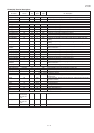
OUTPUT RINGER BUZZER DTMF
ICM/OGM
X0 — — — HIGH
X1 HIGH — —
MIDDLE1
X2 — — —
MIDDLE2
X3
MIDDLE
— HIGH
MIDDLE3
X4 — FIXED
MIDDLE1
—
X5 — —
MIDDLE2
LOW
X6 — —
MIDDLE3
—
X7 LOW — LOW —
• The volume settings of ON-HOOK receiving,
DTMF and ICM/OGM must be performed to-
gether. (The setting of RINGER must be per-
formed separately.)