


UX-258TH
FO-475TH
8 – 2
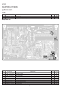
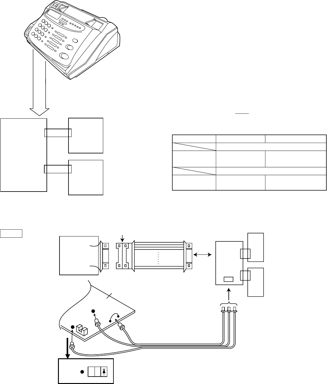
2. Description
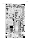
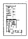
2-1. Relay board unit
1. Remove the TEL/LIU PWB, control PWB and Power Supply PWB
from this unit, and mount the relay board unit instead.
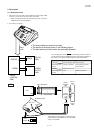
• Before connecting the wiring to the relay board unit, set the test
PWB switches to the fixed position.
2. The setting is as follows.
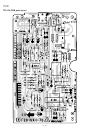
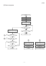
The recording paper sensor (PSNS) is operated by OR of the mechani-
cal unit switch and the test PWB switch. When performing installation in
the machine unit, set the test PWB switches to the fixed position.
Mechanical unit PWB to be tested
Actual operation with mechanical unit
Recording paper
sensor
ON/OFF operation
OFF (Photo interrupter
is interrupted.)
PWB sensor check
Recording paper
sensor
ON/OFF operationOFF
POWER
SUPPLY
PWB
TEL/LIU
PWB
CHECK
CONTROL
PWB
DOOR
SENSOR
RELAY CABLE
DON'T SEPARATE
UNIT
TP3
(PSNS)
TP3
(PSNS)
TP1(DG)
TP2(+5V)
C
K
A
E
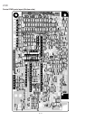
These cables are connected from the extension board
and the checked control PWB at TP1 thru TP3 (signals
of DG, +5V and PSNS).
EXTENSION PWB
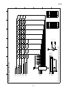
NOTE
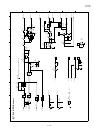
Relay
cable
CNLIUA
CHECK
CONTROL
PWB
TEL/LIU
PWB
12
1
CNPW
CNLIU
POWER
SUPPLY
PWB
• The relay cables are used as one pair.
• The sensor is wired as shown in the following figure.
• The door swich and hook switch are manually operated.