


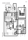
UX-258TH
FO-475TH
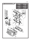
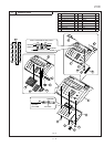
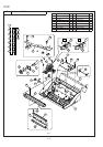
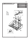
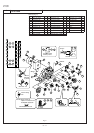
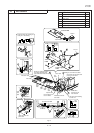
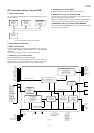
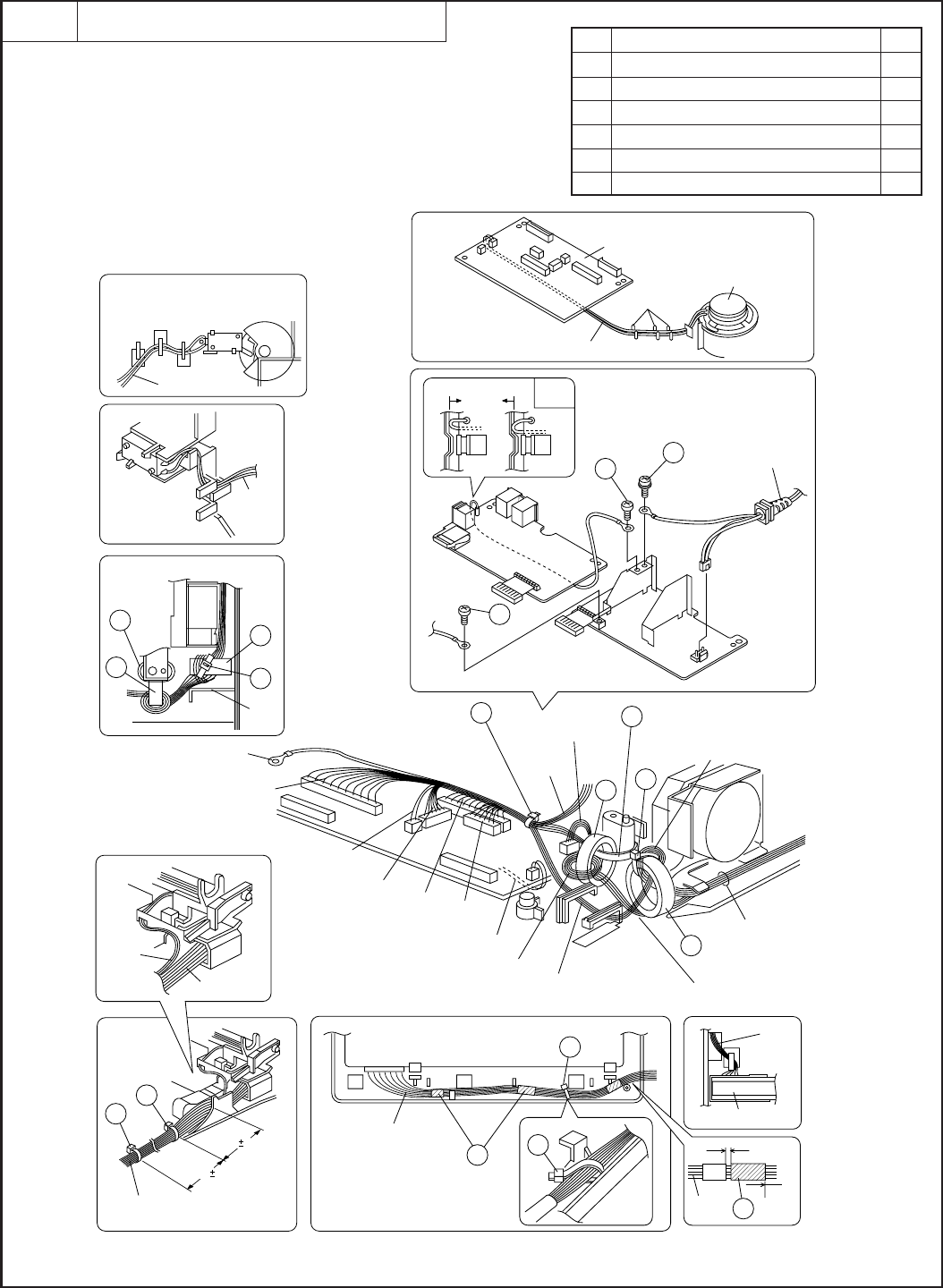
Fig. 10
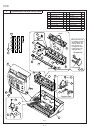
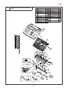
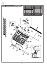
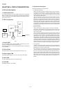
Wire treatment
10
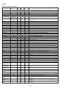
Parts list (Fig. 10)
3 – 12
1 Band (100m) 6
2 Screw (3×6) 2
3 Screw (4×6) 1
4 UL tape 3
5 Core (F2064) 1
6 Core (F2103) 1
No. Part name Q’ty
2
3
Rib
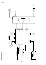
Power supply
PWB
TEL/LIU
PWB
AC cord
ARG
cable
OK NG
Head earth cable
Fixed this switch after adjusting the
cutter gear in this drawing,
Cutter cable
Cutter cable
Cam
switch
cable
Cam
switch
cable
1
1
1
1
100 10mm
20 5mm
Head, head earth and
panel cable
Head cable
Motor
cable
Brinding the cable(Head cable/
Head earth cable/CIS cable/
panel cable/motor cable/cam cable)
Head cable and head
earth cable
Head
earth
cable
Head cable
Operation panel PWB
Panel cable
Panel
cable
CIS
cable
CIS
cable
CIS unit
Speaker cable
1
6
1
1
1
5
1
6
5
Postion of core
Panel cable pass to
the core 2times
The panel cable mustwiring
to under core
All the cables
must wiring to the
motor heat sink
Head cable and head earth cable
pass to the core 2times
Binding the core with lower cabinet
0~2mm
19mm
Panel
cable
4
CIS
cable
2
Rib
Speaker
Speaker cable
Control PWB
4