


ELECTRICAL SPECIFICATION SSD-CXXX(I)-3150 DATA SHEET
SILICONSYSTEMS PROPRIETARY
This document and the information contained within it is confidential and proprietary to SiliconSystems, Inc.
All unauthorized use and/or reproduction is prohibited.
3150C-10DSR PAGE 7FEBRUARY 2, 2009
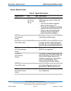
-SPKR
(PC Card I/O
mode)
This line is the Binary Audio output
from the card. If the Card does not
support the Binary Audio function, this
line should be held negated.
-DASP
(True IDE mode)
In the true IDE mode, this input/output
is the Disk Active/Slave Present
signal in the Master/Slave handshake
protocol.
-CD1, -CD2
(PC Card memory
mode)
26, 25 O These Card Detect pins are
connected to ground on the
SiliconDrive CF, and are used by the
host to determine that the SiliconDrive
CF is fully inserted into its socket.
-CD1, -CD2
(PC Card I/O
Mode)
This signal is the same for all modes.
-CD1, -CD2
(True IDE mode)
This signal is the same for all modes.
-CE1, -CE2
(PC Card memory
mode)
Card Enable
7, 32 I These input signals are used both to
select the card and to indicate to the
card whether a byte or a word
operation is being performed.
• -CE2 always accesses the odd
byte of the word.
• -CE1 accesses the even byte or
the odd byte of the word depending
on A0 and -CE2.
A multiplexing scheme based on A0,
-CE1, and -CE2 allows 8-bit hosts to
access all data on D0-D7. See
"Attribute Memory Read Operations"
on page 22, "Attribute Memory Write
Operations" on page 23, "Common
Memory Read Operations" on page
40, and "Common Memory Write
Operations" on page 40.
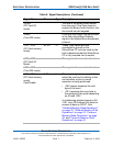
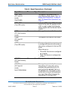
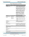
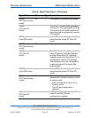
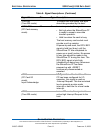
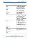
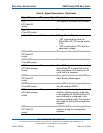
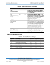
Table 8: Signal Descriptions (Continued)
Signal Name Pin Type Description