


ELECTRICAL SPECIFICATION SSD-CXXX(I)-3150 DATA SHEET
SILICONSYSTEMS PROPRIETARY
This document and the information contained within it is confidential and proprietary to SiliconSystems, Inc.
All unauthorized use and/or reproduction is prohibited.
3150C-10DSR PAGE 11 FEBRUARY 2, 2009
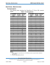
-ATA SEL
(True IDE mode)
To enable true IDE mode, this input
should be grounded by the host.
-RDY/-BSY
(PC Card memory
mode)
37 O In memory mode, this signal is:
• Set high when the SiliconDrive CF
is ready to accept a new data
transfer operation.
• Held low when the card is busy.
The host memory card socket must
provide a pull-up resistor.
At power-up and reset, the RDY/-BSY
signal is held low (busy) until the
SiliconDrive CF has completed its
power-up or reset function. No access
of any type should be made to the
SiliconDrive CF during this time. The
RDY/-BSY signal is held high
(disabled from being busy) whenever
the SiliconDrive CF has been
powered up with +RESET
continuously disconnected or
asserted.
-IREQ
(PC Card I/O
mode)
Input Acknowledge
I/O Operation. After the SiliconDrive
CF has been configured for I/O
operation, this signal is used as
-Interrupt Request. This line is strobed
low to generate a pulse mode
interrupt or held low for a level mode
interrupt.
-IREQ
(True IDE mode)
In true IDE mode, this signal is the
active high Interrupt Request to the
host.
Table 8: Signal Descriptions (Continued)
Signal Name Pin Type Description