


ELECTRICAL SPECIFICATION SSD-CXXX(I)-3150 DATA SHEET
SILICONSYSTEMS PROPRIETARY
This document and the information contained within it is confidential and proprietary to SiliconSystems, Inc.
All unauthorized use and/or reproduction is prohibited.
3150C-10DSR PAGE 8FEBRUARY 2, 2009
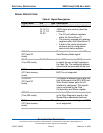
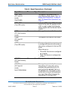
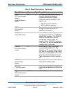
-CE1, -CE2
(PC Card I/O
mode)
Card Enable
This signal is the same as the PC
Card Memory Mode signal. See "I/O
Space Read Operations" on page 41
and "I/O Space Write Operations" on
page 41.
-CS0, -CS1
(True IDE mode)
In the true IDE mode, -CS0 is the chip
select for the task file registers while
-CS1 is used to select the Alternate
Status register and the Device Control
register.
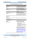
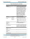
-CSEL
(PC Card memory
mode)
39 I This signal is not used for this mode.
-CSEL
(PC Card I/O
mode)
This signal is not used for this mode.
-CSEL
(True IDE mode)
This internally pulled-up signal is used
to configure this device as a master or
slave when configured in the true IDE
mode.
When this pin is:
• Grounded, this device is configured
as a master.
• Open, this device is configured as
a slave.
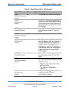
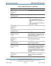
-INPACK
(PC Card memory
mode)
43 O This signal is not used in this mode.
-INPACK
(PC Card I/O
mode)
Input Acknowledge
This signal is asserted by the
SiliconDrive CF when the card is
selected and responding to an I/O
read cycle at the address that is on
the address bus. This signal is used
by the host to control the enabling of
any input data buffers between the
SiliconDrive CF and the CPU.
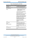
Table 8: Signal Descriptions (Continued)
Signal Name Pin Type Description