


ELECTRICAL SPECIFICATION SSD-CXXX(I)-3150 DATA SHEET
SILICONSYSTEMS PROPRIETARY
This document and the information contained within it is confidential and proprietary to SiliconSystems, Inc.
All unauthorized use and/or reproduction is prohibited.
3150C-10DSR PAGE 13 FEBRUARY 2, 2009
V
CC
(PC Card I/O
mode)
This signal is the same for all modes.
V
CC
(True IDE mode)
This signal is the same for all modes.
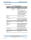
-VS1, -VS2 33, 40 O Voltage Sense Signals.
• -VS1 is grounded so that the
SiliconDrive CF CIS can be read at
3.3V.
• -VS2 is reserved by PC Card for a
secondary voltage.
-VS1, -VS2
(PC Card I/O
mode)
This signal is the same for all modes.
-VS1, -VS2
(True IDE mode)
This signal is the same for all modes.
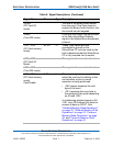
-WAIT
(PC Card memory
mode)
42 O The -WAIT signal is driven low by the
SiliconDrive CF to signal the host to
delay completion of a memory or I/O
cycle that is in progress.
-WAIT
(PC Card I/O
mode)
This signal is the same as the PC
Card Memory Mode signal.
-IORDY
(True IDE mode)
In true IDE mode, this output signal
may be used as IORDY.
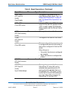
-WE
(PC Card memory
mode)
36 I This is a signal driven by the host and
used for strobing memory write data
to the registers of the SiliconDrive CF
when the card is configured in the
memory interface mode. This signal is
also used for writing the configuration
registers.
-WE
(PC Card I/O
mode)
In PC Card I/O mode, this signal is
used for writing the configuration
registers.
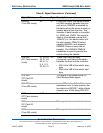
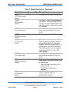
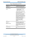
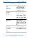
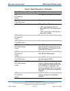
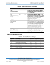
Table 8: Signal Descriptions (Continued)
Signal Name Pin Type Description