


ATTRIBUTE MEMORY DESCRIPTION AND OPERATION SSD-CXXX(I)-3150 DATA SHEET
SILICONSYSTEMS PROPRIETARY
This document and the information contained within it is confidential and proprietary to SiliconSystems, Inc.
All unauthorized use and/or reproduction is prohibited.
3150C-10DSR PAGE 37 FEBRUARY 2, 2009
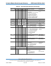
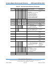
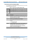
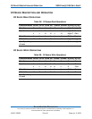
CONFIGURATION AND STATUS REGISTER (202H)
The Configuration and Status Register (CSR) informs the host of any status
changes with regard to power-down.
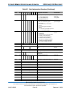
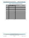
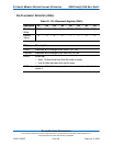
Table 23: Configuration and Status Register (202h)
Operation
D
7
D
6
D
5
D
4
D
3
D
2
D
1
D
0
Read Changed SigChg IOis8 0 0 PwrDn Int 0
Write Changed SigChg IOis8 0 0 PwrDn Int 0
Default
Value
0 0 000000
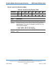
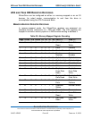
Bit(s) Description
Changed Indicates that either CREADY (D5) or CWPort (D4) of the Pin
Replacement register is set. Additionally, this bit changes state
as the Powerdown (D2) bit changes.
SigChg Outputs the inverse state of the Changed bit to the hardware
interface signal STSCHG# at the card interface.
Iois8 Informs the host of the valid data bus width for the operations in
progress:
• 0 = 16-bit data transfer
• 1 = 8-bit data transfer
PwrDwn Indicates the state of the Card, which is either operating -0 or
powerdown mode 1. During powerdown mode, no commands
are accepted. Additionally, the host may not initiate a
powerdown request when the card is busy via the Status
register or the Hardware RDY/BSY pin.
Int Indicates the inverse of the IREQ# status signal.