


ELECTRICAL SPECIFICATION SSD-DXXX(I)-4210 DATA SHEET
SILICONSYSTEMS PROPRIETARY
This document and the information contained within it is confidential and proprietary to SiliconSystems, Inc.
All unauthorized use and/or reproduction is prohibited.
4210D-03DSR PAGE 25 FEBRUARY 2, 2009
t
DVS
70 - 48 - 30 - 20 - 6 - Data valid setup time at
sender (from data valid until
STROBE edge) (see Note 4).
ns
t
DVH
6 - 6 - 6 - 6 - 6 - Data valid hold time at sender
(from STROBE edge until
data may become invalid)
(see Note 4).
ns
t
FS
0 230 0 200 0 170 0 130 0 120 First STROBE time (for
device to first negate
DSTROBE from STOP during
a data-in burst).
ns
t
LI
0 150 0 150 0 150 0 100 0 100 Limited interlock time (see
Note 3).
ns
t
MLI
20 - 20 - 20 - 20 - 20 - Interlock time with minimum
(see Note 3).
ns
t
UI
0 - 0 - 0 - 0 - 0 - Unlimited interlock time (see
Note 3).
ns
t
AZ
- 10 - 10 - 10 - 10 - 10 Maximum time allowed for
output drivers to release
(from asserted or negated).
ns
t
ZAH
20 - 20 - 20 - 20 - 20 - Minimum delay time required
for output.
ns
t
ZAD
0 - 0 - 0 - 0 - 0 - Drivers to assert or negate
(from released).
ns
t
ENV
20 70 20 70 20 70 20 55 20 55 Envelope time (from DMACK-
to STOP and HDMARDY-
during data-in burst initiation,
and from DMACK to STOP
during data-out burst
initiation).
ns
t
SR
- 50 - 30 - 20 - NA - NA STROBE to DMARDY- time
(if DMARDY- is negated
before this long after
STROBE edge, the recipient
receives no more than one
additional data word).
ns
t
RFS
- 75 - 70 - 60 - 60 - 60 Ready-to-final STROBE time
(no STROBE edges are sent
this long after negation of
DMARDY-).
ns
t
RP
160 - 125 - 100 - 100 100 - Minimum time to assert STOP
or negate DMARQ.
ns
t
IORDYZ
- 20 - 20 - 20 - 20 - 20 Maximum time before
releasing IORDY.
ns
t
ZIORDY
0 - 0 - 0 - 0 - 0 - Minimum time before driving
STROBE (see note 5).
ns
t
ACK
20 - 20 - 20 - 20 - 20 - Setup and hold times for
DMACK- (before assertion or
negation).
ns
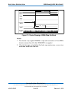
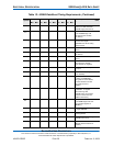
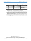
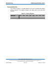
Table 13: UDMA Data Burst Timing Requirements (Continued)
Symbol
Mode 0 Mode 1 Mode 2 Mode 3 Mode 4
Comment (see Notes 1 and
2)
Units
Min. Max. Min. Max. Min. Max. Min. Max. Min. Max.