Si53xx-RM
74 Rev. 0.5
6.9.3. FSYNC Align Alarm (Si5366 and CK_CONF = 1 and FRQTBL = L)
At power-up or any time after the PLL has lost lock and relocked, the device automatically performs a realignment
of FS_OUT using the currently active sync input. After this, as long as the PLL remains in lock and a realignment is
not requested, FS_OUT will include a fixed number of high-speed clock cycles, even if input clock switches are
performed. If many clock switches are performed, it is possible that the input sync to output sync phase relationship
will shift due to the accumulated residual phase transients of the phase build-out circuitry. The internal ALIGN_INT
signal is asserted when the accumulated phase errors exceeds two cycles of CKOUT2.
6.9.4. C1B and C2B Alarm Outputs (Si5316, Si5322, Si5323)
The alarm outputs (C1B and C2B) are determined directly by the LOS1_INT and LOS2_INT internal indicators
directly. That is C1B = LOS1 and C2B = LOS2.
6.9.5. C1B, C2B, C3B, and ALRMOUT Outputs (Si5365, Si5366)
The alarm outputs (C1B, C2B, C3B, ALRMOUT) provide a summary of various alarm conditions on the input clocks
depending on the setting of the FOS_CNTL and CK_CONF pins.
The following internal alarm indicators are used in determining the output alarms:
LOSn_INT: See section “6.9.1. Loss-of-Signal Alarms (Si5316, Si5322, Si5323, Si5365, Si5366)” for a
description of how LOSn_INT is determined
FOSn_INT: See section “6.9.2. FOS Alarms (Si5365 and Si5366)”for a description of how FOSn_INT is
determined
ALIGN_INT: See section “6.9.3. FSYNC Align Alarm (Si5366 and CK_CONF = 1 and FRQTBL = L)” for a
description of how ALIGN_INT is determined
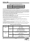
Based on the above internal signals and the settings of the CK_CONF and FOS_CTL pins, the outputs C1B, C2B,
C3B, ALRMOUT are determined (See Table 33). For details, see "Appendix D—Alarm Structure" on page 144.
.
Table 32. Frequency Offset Control (FOS_CTL)
FOS_CNTL Meaning
L FOS Disabled.
M Stratum 3/3E FOS Threshold (12 ppm)
H SONET Minimum Clock Threshold (48 ppm)
Table 33. Alarm Output Logic Equations
CK_CONF FOS_CTL Alarm Output Equations
0
Four independent input
clocks
L
(Disables FOS)
C1B = LOS1_INT
C2B = LOS2_INT
C3B = LOS3_INT
ALRMOUT = LOS4_INT
M or H C1B = LOS1_INT or FOS1_INT
C2B = LOS2_INT or FOS2_INT
C3B = LOS3_INT or FOS3_INT
ALRMOUT = LOS4_INT or FOS4_INT
1
(FSYNC switching
mode)
L
(Disables FOS)
C1B = LOS1_INT or (LOS3_INT and FSYNC_SWTCH)
C2B = LOS2_INT or (LOS4_INT and FSYNC_SWTCH)
C3B = tri-state
ALRMOUT = ALIGN_INT
M or H C1B = LOS1_INT or (LOS3_INT and FSYNC_SWTCH) or FOS1_INT
C2B = LOS2_INT or (LOS4_INT and FSYNC_SWTCH) or FOS2_INT
C3B = tri-state
ALRMOUT = ALIGN_INT


