


CPD-E400/E400E
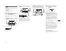
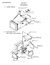
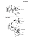
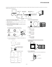
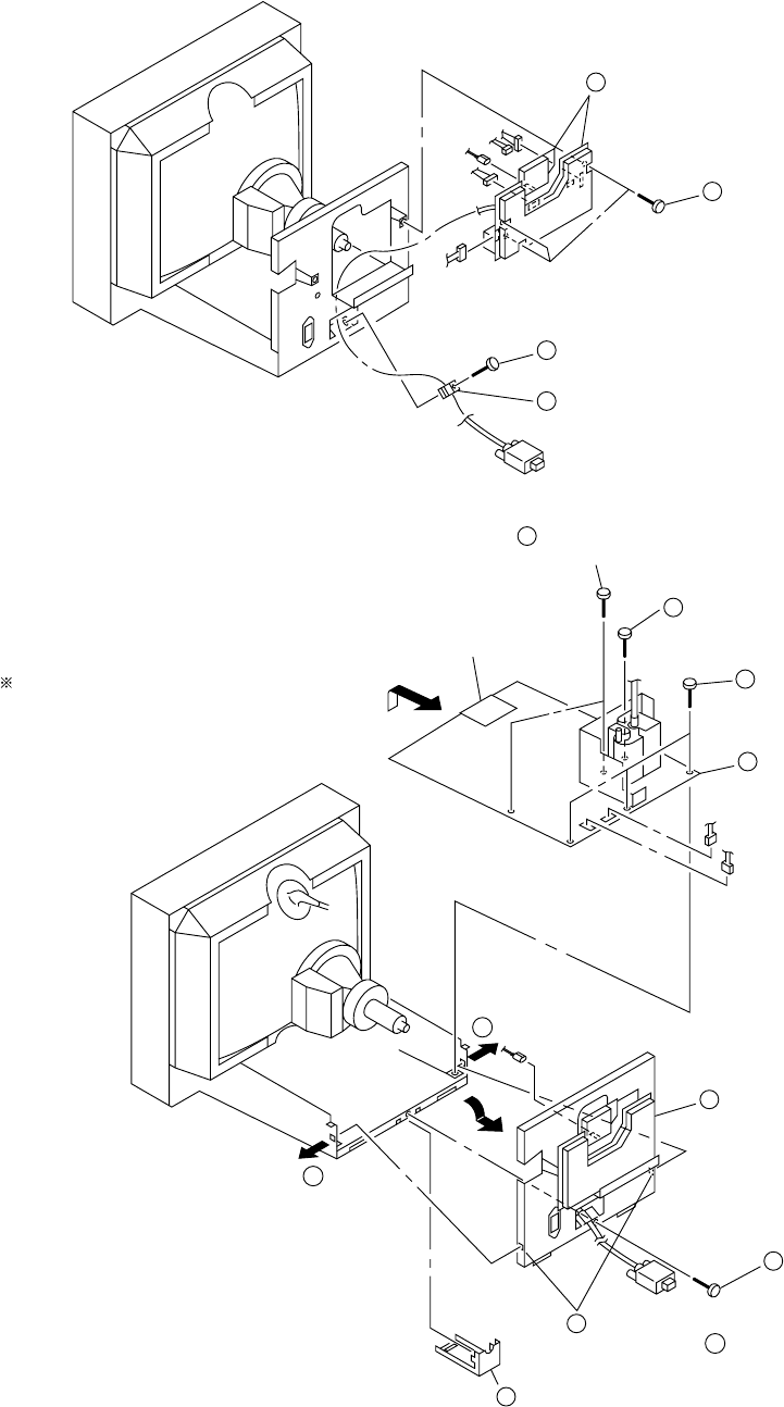
2-3. A BOARD REMOVAL
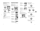
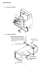
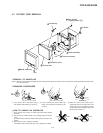
2-4. REAR SHIELD COMPLETE ASSY,
D BOARD REMOVAL
2-2
3
Three screws
(+BVTT 3 x 8)
4
A board
CN306
CN311
CN303
CN309
CN305
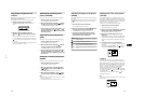
1
Screw
(+BVTT 4 x 8)
2
Cable stopper
5
Three screws
(+BVTT 3 x 8)
CN601
CN600
CN303
8
D board
N board
6
Screw
(+P 3.5 x 20)
7
Two screws
(+BVTP 3 x 8)
2
Screw
(+BVTT 4 x 8)
4
Rear shield
complete assembly
1
Cable cover
3
Widening the chassis toward
the direction A , disengage
two claws.
A
A
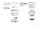
Refering to 2-3, disconnect five connectors
(CN303, CN305, CN306, CN309 and CN311).