


CPD-E400/E400E
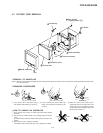
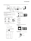
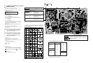
Connect the communication cable of the computer to the connector located on the D board on the monitor. Run the service software
and then follow the instruction.
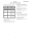
IBM AT Computer
as a Jig
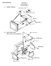
1-690-391-21
1
A-1500-819-A
Interface Unit
2
*The parts above ( ) are necessary for DAS adjustment.
1
3
D-sub
(9 Pin [female])
mini Din
(8Pin)
4 Pin
3-702-691-01
Connector Attachment
3
To BUS CONNECTOR
4 Pin 4 Pin
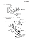
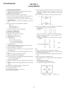
• Convergence Rough Adjustment
(1) Receive an image of the white crosshatch signals (white
lines on black).
(2) Make rough adjustment of the H and V direction conver-
gence by using 4-fold poles magnet.
(3) Make rough adjustment of the HMC and VMC by using 6-
fold poles magnet.
<“0” position of each magnet and TLH plate>
a) Align the protrusion marked with an arrow.
• White Balance Adjustment Specification
1. 9300 K
x = 0.283 ± 0.005
y = 0.298 ± 0.005
(All White)
2. 5000 K
x = 0.346 ± 0.005
y = 0.359 ± 0.005
(All White)
3. sRGB
x = 0.313 ± 0.005
y = 0.329 ± 0.005
(All White)
• Vertical and Horizontal Position and Size
Specification
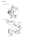
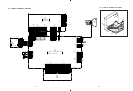
• Focus adjustment
Adjust the focus volume 1 and 2 for the optimum focus.
• Convergence Specification
4-2
[2-fold poles
magnet on the DY]
[4-fold poles magnet]
[6-fold poles magnet]
[2-fold poles magnet
on neck assy]
b) Flush the shaded portions of TLH plate with the DY rear
cover, as shown below.
TLH
plate
XCV
TLV
DY rear cover
TLH plate
[Rear view]
[Movements of TLH plate]
[Movements of XCV volume]
2-fold poles magnet
4-fold poles magnet
6-fold poles magnet
or
or
B
A
A
0.20 mm
B
All mode
0.24 mm
V
MODE
B
a
a 2.0 mm
b 2.0 mm
a
b
b
A
MODE
A
B
352 mm
264 mm
All mode
FOCUS 1
FOCUS 2
FBT ASSY