


CPD-E400/E400E
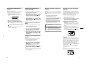
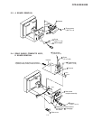
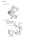
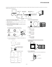
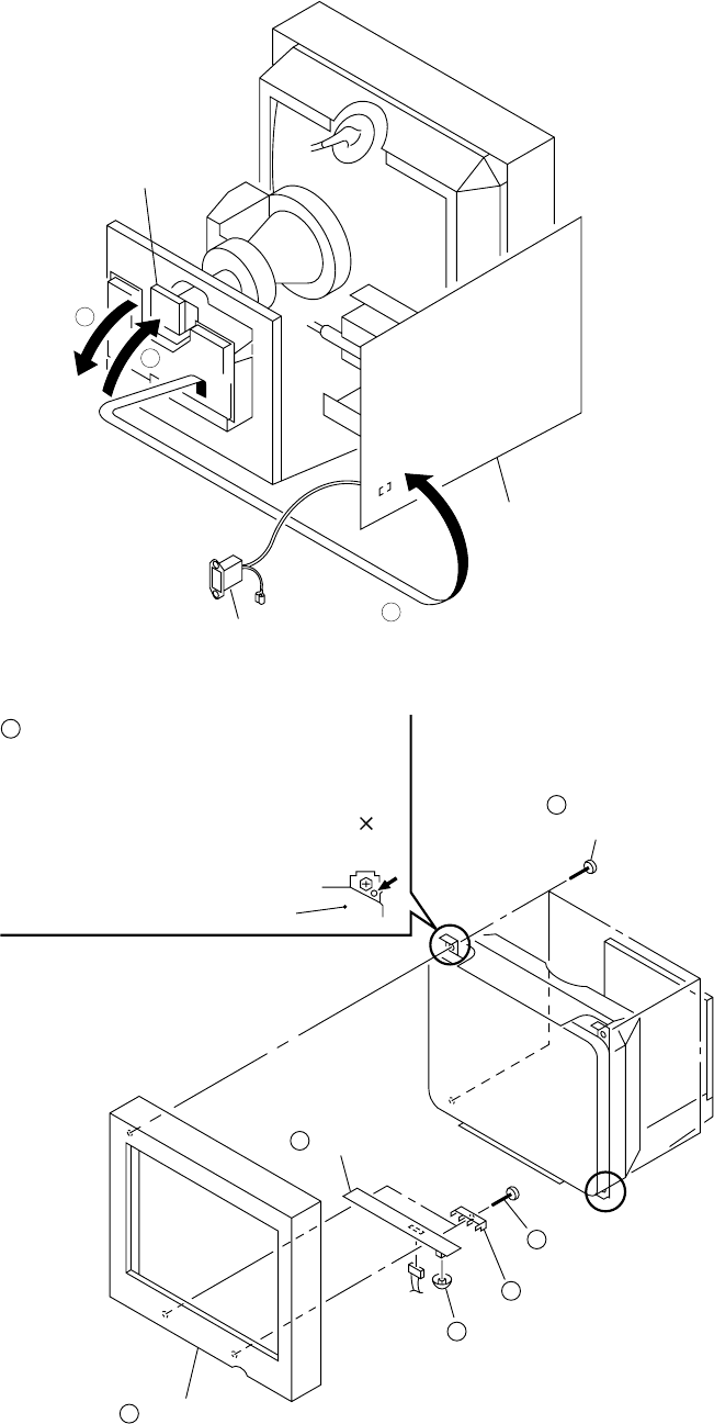
2-6. H BOARD REMOVAL
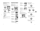
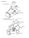
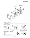
2-5. SERVICE POSITION
2-3
AC inlet
D board
A board
1
2
3
Four screws
(Tapping screw (5))
H board
Two screws
(+ BVTP 4 x 16)
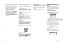
Bezel assembl
y
Two H printed circuit
board brackets
Menu button
CN801
Picture tube shield
Before removing the bezel assembly,
secure the picture tube shield at the
positions shown with the arrow (diagonal
two places) to prevent the picture tube
from falling. (Use the screws +BVTT 4 8
that fix shield.)
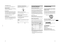
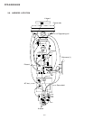
3
6
7
5
4
2
1