


CPD-E400/E400E
– 5 –
TABLE OF CONTENTS
Section Title Page
1. GENERAL ................................................................. 1-1
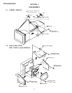
2. DISASSEMBLY
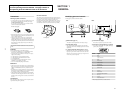
2-1. Cabinet Removal ................................................ 2-1
2-2. Shield (EMI, Video),
Side Cover (L and R) Removal.......................... 2-1
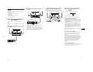
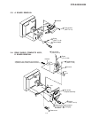
2-3. A Board Removal ............................................... 2-2
2-4. Rear Shield Complete Assy,
D Board Removal ............................................... 2-2
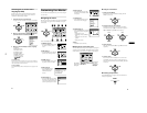
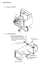
2-5. Service Position .................................................. 2-3
2-6. H Board Removal ............................................... 2-3
2-7. Picture Tube Removal........................................ 2-4
2-8. Harness Location ................................................ 2-5
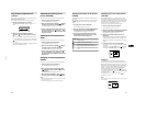
3. SAFETY RELATED ADJUSTMENT............. 3-1
4. ADJUSTMENTS ..................................................... 4-1
5. DIAGRAMS
5-1. Block Diagrams .................................................. 5-1
5-2. Frame Schematic Diagram ................................. 5-5
5-3. Circuit Boards Location ..................................... 5-6
5-4. Schematic Diagrams and Printed Wiring
Boards ................................................................. 5-7
(1) Schematic Diagram of A Board ......................... 5-9
(2) Schematic Diagrams of D (a,b,c) Board.... 5-11
(3) Schematic Diagrams of N, H Boards................. 5-19
5-5. Semiconductors .................................................. 5-21
6. EXPLODED VIEWS
6-1. Chassis ................................................................ 6-1
6-2. Picture Tube........................................................ 6-2
6-3. Packing Materials ............................................... 6-3
7. ELECTRICAL PARTS LIST ............................ 7-1