


CPD-E400/E400E
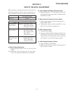
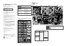
Part Replaced (])
D Board T901(FBT), IC901,
R924, R925, RV901
• Mounted D board
D Board T901(FBT), R917,
R918, R923, R920,
R919, R1004, C920,
D911, R912,
• Mounted D board
D Board R933, R932, R921,
R1006, D915, D917,
IC901, T901(FBT)
• Mounted D board
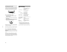
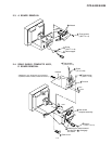
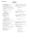
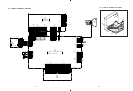
b) High Voltage Hold-Down Function Check
1) Apply the voltage 21.1 VDC between D912 cath-
ode and GND shown on the right to confirm that the
RASTER will vanish.
c) Beam Current Protector Function Check
1) Connect Power Supply 1.68 mA to between pin 11 ~
GND of FBT (T901).
2) Confirm that voltage on C922 (ABL DET.) is less
than 2.25 V or monitor will shut down.
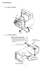
d) OCP Function Check
1) Turn ON Power Supply.
2) Connect 3 Z/20 W of Resistor between +200 V Line
and GND, and make sure that OCP will function
(Power LED will vanish and the sound “chi,chi,chi
will be heard.), and cut-off AC input promptly.
e) Power Supply Operation Check
1) Apply AC100 V to the D Board.
2) Make sure that the line voltage at the both ends of
C621 is 200 ± 3.0 VDC.
HV Regulator
Circuit Check
HV Protector
Circuit Check
Beam Current
Protector Circuit
Check
When replacing or repairing the shown below table, the
following operational checks must be performed as a
safety precaution against X-rays emissions from the unit.
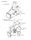
SECTION 3
SAFETY RELATED ADJUSTMENT
3-1
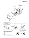
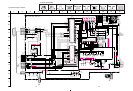
Part Replaced ([)
RV901
HV ADJ
* Confirm one minute after turning on the power.
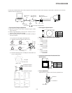
a) High Voltage Adjustment
1) Adjust the high voltage 27.0 kV ± 0.2 kV by the
RV901.
Note:Perform high voltage adjustment after the rough adjust-
ments were completed on PICTURE size and FOCUS.
+ 0.00
– 0.05