


12
D:\JN\KP-53HS10\KP53HS10GB\407416311KP53HS10USA\02US-KP53HS10USA\06INT.fm masterpage:Left
Model name1[KP-53HS10] Model name2[KP-61HS10]
[4-074-163-11 (1)]
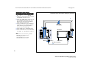
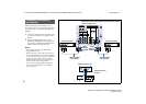
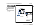
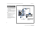
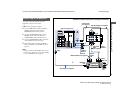
Disconnect all power sources before making any connections.
C
CC
Connec
onneconnec
onnect
tt
ti
ii
ing a
ng a ng a
ng a D
DD
DT
TT
TV
V V
V (
((
(d
dd
di
ii
ig
gg
gi
ii
it
tt
ta
aa
al
l l
l
t
tt
te
ee
el
ll
le
ee
ev
vv
vi
ii
is
ss
si
ii
ion
onon
on)
) )
) r
rr
rece
eceece
ecei
ii
iv
vv
ve
ee
er
r r
r w
ww
wi
ii
it
tt
th
h h
h t
tt
the
he he
he Y
YY
Y/
//
/P
PP
P
B
BB
B
/
//
/
P
PP
P
R
RR
R
(
((
(co
coco
com
mm
mponen
ponenponen
ponent
t t
t v
vv
vi
ii
ideo
deo deo
deo i
ii
inpu
npunpu
nput
tt
t)
) )
) j
jj
jack
ackack
acks
ss
s
1
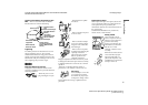
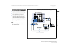
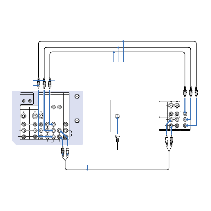
Attach the coaxial cable from the roof antenna
to VHF/UHF on the DTV receiver.
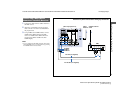
2
Using three VIDEO cables, connect Y, P
B
and
P
R
of COMPONENT VIDEO OUT on the
DTV receiver to Y, P
B
and P
R
of VIDEO 5
(DTV) IN on the projection TV.
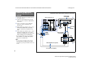
3
Using an AUDIO cable, connect LINE OUT
on the DTV receiver to AUDIO of VIDEO 5
(DTV) IN on the projection TV (White-
AUDIO Left, Red-AUDIO Right).
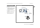
4
Select VIDEO 5 by the TV/VIDEO button.
5
Select the SET UP menu and set DTV INPUT
to Y PB PR. (see “DTV INPUT” on page 43)
Note:
• Some DTV receiver terminals may be labeled
differently. If so, connect as follows:
Connect Y (green) to Y.
Connect P
B
(blue) to C
B
, C
b
or B-Y.
Connect P
R
(red) to C
R
, C
r
or R-Y.
S VIDEO
1
VIDEO
L
R
VHF/UHF
(DTV)
(MONO)
AUDIO OUT
2Y
P
B
PR
1 2 3
VIDEO OUT
S VIDEO
VIDEO
AUDIO
L
R
R
VIDEO
(MONO)
IN
IN
CONTROL S
IN OUT
OUT
VIDEO 4
VIDEO 1 VIDEO 3
VIDEO 5 (DTV)
SELECT
Y
P
B
PR
Y/G
HD VD
P
B/B
P
R/R
L
(MONO)
R
L
AUDIO
AUDIOCOMPONENT
VHF/UHF
AUX
3
2
1
VMC-10HG
(not supplied)
AUDIO-L
RK-74A (not supplied)
Y
AUDIO-R
P
B
P
R
DTV receiver
Roof Antenna