Configuring the MP Modem to Report GPS and I/O
Data
Rev 1.5 Jul.08 55
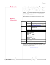
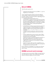
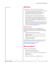
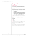
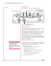
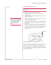
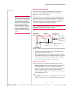
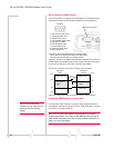
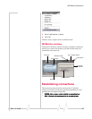
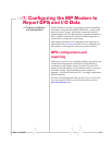
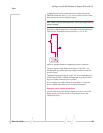
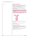
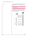
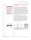
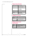
Adigitalinputcanbeconnectedtofourofthepinsonthe
DB15HDconnector:Pins3,4,11,and12.(Pins3and11could
alternativelybeusedfordigitaloutput.)
Note: Before using the input/output lines, you must configure them as
inputs or outputs.
Typicallyadigitalinputdeviceshouldbeconnectedbetween
Ground(Pin10)andtheinpu tport(Pin3,4,11,or12).
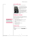
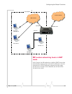
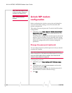
Figure 7-2: A button wired to Pin 4 (digital input) and Pin 10 (Ground).
Thepinsreportalogichighonaninputof3.45VDC.An
internalpull‐upresistorprovidesahighconditionwhenthe
switchisopen.
Thedigitalinputpinsreportalogiclowonaninputbetween
0
VDCand0.8VDC.Sinkingtheinputpintogroundyieldsa
logiclow(0x00)whentheportispolled.
IfyouconfiguretheMPmodemtosenddatatoanetwork
server,digitalinputdatacanberemotelymonitored.
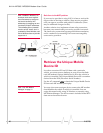
Example: panic button connections
AnI/Ocableforapanicbuttonrequiresawiretooneofthe
digitalinputorI/Opins(suchas#3)andonewiretothe
Groundpin(#10).