


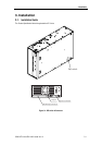
3.Installation
3-2 SONY AIT-5 drive SDX-1100V series Ver.1.0
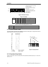
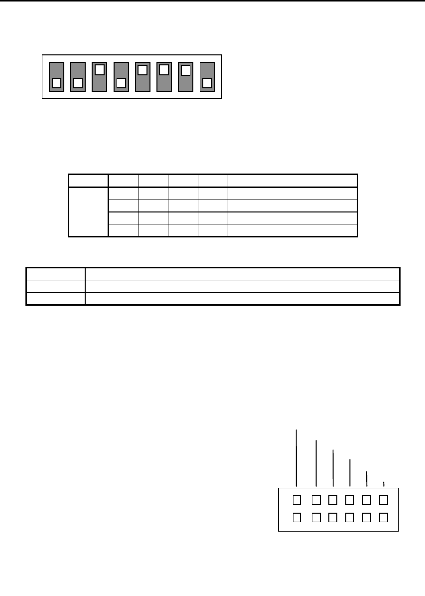
1 DR (Desaster Recovery) Mode
2 Emulation Mode
3 AIT Library Interface Mode
4 Reserved
5 Terminator Power (ON)
6 Periodic Cleaning Req (ON)
7 DC Control-1
8 DC Control-2
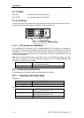
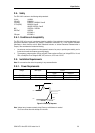
1 2 3 4 5 6 7 8
ON
OFF
Figure 3-2: DIP Switch Positions
Table 3-1: Drive Mode
DIP SW 1 2 3 4 MODE
OFF OFF
ON
OFF
Normal
ON OFF
OFF
OFF
DR Mode
OFF ON OFF
OFF
SDX-900V Emulation Mode
OFF OFF
ON
OFF
Library Mode
Table 3-2: Periodic Cleaning Request (Refer to 4.6.1.2)
DIP SW 6 Definition
OFF Disable Periodic Cleaning Request
ON Enable Periodic Cleaning Request
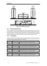
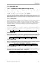
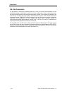
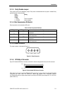
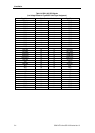
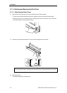
3.1.1. SCSI ID Number Jumper
The SCSI ID number of the SDX-1100V is selected by the SCSI ID number jumpers. The figure below shows the
jumper configuration for each of the possible SCSI IDs.
3.1.2. Termination Power Switch
Position 5 of DIP switch is used to set whether SDX-1100V provides the termination power to pin 17,18,51,52 on
SCSI bus, or not.
SCSI ID3 ID2 ID1 ID0
0 : : : :
1 : : : |
2 : : | :
3 : : | |
4 : | : :
5 : | : |
6 : | | :
7 : | | |
8 | : : :
9 | : : |
10 | : | :
11 | : | |
12 | | : :
13 | | : |
14 | | | :
15 | | | |
: = OPEN Jumper not installed
|
= CLOSED Jum
p
er installed
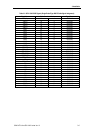
Parity Disable
No Connection
ID3
ID2
ID1
ID0
Figure 3-3: Jumper positions