


6.Command Specification MODE SELECT
6-42 SONY AIT-5 drive SDX-1100V series Ver.1.0
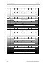
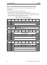
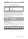
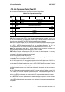
Density Code: The supported values for the density code field are defined in the following table.
Table 6-40: Sequential-Access Density Codes
Code Value Code Value
30h
31h
32h
B3h
33h
34h
7Fh
AIT-1 Format (not support)
AIT-2 Format (not support)
AIT-3 Format
AIT-3Ex Format
AIT-4 Format
AIT-5 Format
No change from previous density
Number of Blocks: A MODE SENSE field which will be returned as ZERO, indicating that all of the remaining
logical blocks on the media will have the medium characteristics specified by the block descriptor, or until a
subsequent MODE SELECT command changes those parameters. This field must be set to ZERO on a MODE
SELECT otherwise a CHECK CONDITION status will be returned with an ILLEGAL REQUEST sense key.
Block length: The Block Length field specifies the length in bytes of each logical block. A block length of ZERO
indicates that the length is variable. Any other value indicates the number of bytes per block that the drive must
handshake over the bus. This establishes block length such that the transfer length for read, write type commands
will be a block count not a byte count.
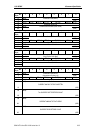
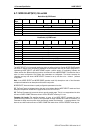
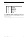
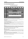
Note: It is value of this field together with the Fixed bit Field in the READ, or WRITE commands that determine
whether the drive is in Fixed or Variable block mode.
Mode Fixed Bit in Read, Write Block Length in
Mode Select/Sense
Fixed Block
Variable Block
1
0
Block Size
0
The default fixed block size is 0 bytes however, if a fixed command (fixed bit of ONE) is received, the drive will
return the CHECK CONDITION status with an ILLEGAL REQUEST sense key and the ASC will be set to
COMMAND SEQUENCE ERROR.
Note: Minimum block-size is 4. The figures must be multiples of 4, otherwise CHECK CONDITION status will be
returned with an ILLEGAL REQUEST sense key.
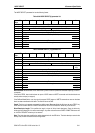
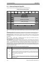
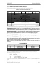
Following the Block Descriptor are the MODE SELECT pages. They are the method by which the device
parameters are set. Each page has a two byte header which identifies the page code and indicates the number of
bytes in that page.
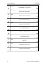
Table 6-41: MODE SELECT Page Header
Bit
Byte
7 6 5 4 3 2 1 0
0 PS Reserved Page Code
1 Additional Page Length
PS: when the Page Savable bit is set, this indicates that the page contains saved parameters. This bit will never
be set as there is no non-volatile RAM on the drive into which parameter data may be saved.