


Step 1: Installing the Projector
Connections and
Preparations
GB
12
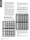
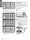
To calculate the installation measurements (SS: Screen Size)
a (minimum) ={(SS × 33.56/0.8788) – 56.520408} × 1.025
a (maximum) ={(SS × 42.3591819/0.8788) – 57.181415} × 0.975
x = b + (SS/0.8788 × 5.516)
When using the 4:3 aspect ratio screen
Unit: mm (inches)
To calculate the installation measurements (SS: Screen Size)
a (minimum) ={(SS × 33.56/0.7240) – 58.520408} × 1.025
a (maximum) ={(SS × 42.3591819/0.7240) – 57.181415} × 0.975
x = b + (SS/0.7240 × 5.516)
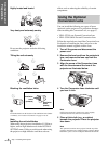
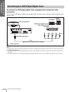
Attaching the projector suspension
support PSS-610
When installing the projector on the ceiling, use the
PSS-610 Projector Suspension Support. For more
details on the ceiling installation, refer to the
Installation manual for Dealers of the PSS-610. The
installation measurements are shown below when you
install the projector on the ceiling.
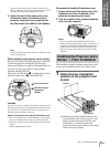
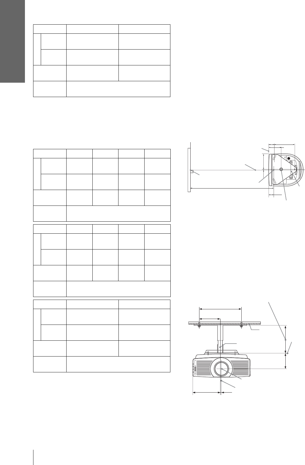
Installation diagram
Top view
Align the center of the lens with the center of the
screen.
Front view
The lens is offset 7.9 mm (
5
/16 inch) to the right from
the center of the supporting pole. When mounting,
take care to align the center of the lens with the center
of the screen; not the center of the supporting pole.
SS (inches) 250 300
a
Minimum
9730
(383
1
/8)
11680
(460
3
/8)
Maximum
11690
(460
3
/8)
14040
(552
7
/8)
x
b+1569
(b+61
7
/8)
b+1883
(b+74
1
/4)
b
When using the PSS-610, adjustable with
243/268/293/343/368/393 mm
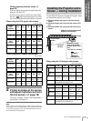
SS (inches) 40 60 80 100
a
Minimum
1840
(72
1
/2)
2790
(109
7
/8)
3740
(147
3
/8)
4690
(184
3
/4)
Maximum
2230
(87
7
/8)
3370
(132
3
/4)
4510
(177
5
/8)
5650
(222
1
/2)
x
b+305
(b+12)
b+457
(b+18)
b+609
(b+24)
b+762
(b+30)
b
When using the PSS-610, adjustable with
243/268/293/343/368/393 mm
SS (inches) 120 150 180 200
a
Minimum
5640
(222
1
/8)
7070
(278
1
/2)
8490
(334
3
/8)
9440
(371
3
/4)
Maximum
6790
(267
3
/8)
8500
(334
3
/4)
10210
(402
1
/8)
11350
(447)
x
b+914
(b+36)
b+1143
(b+45)
b+1371
(b+54)
b+1524
(b+60)
b
When using the PSS-610, adjustable with
243/268/293/343/368/393 mm
SS (inches) 250 300
a
Minimum
11820
(465
1
/2)
14190
(558
3
/4)
Maximum
14200
(559
1
/8)
17060
(671
3
/4)
x
b+1905
(b+75)
b+2286
(b+90)
b
When using the PSS-610, adjustable with
243/268/293/343/368/393 mm
62.1
(2
1
/
2
)
61.5
(2
1
/
2
)
216.6
(8
5
/
8
)
134.2
(5
3
/
8
)
165
(6
1
/
2
)
7.9
(
5
/
16
)
Front of the cabinet
Center of the unit
Center of the lens
Center of the screen
Distance between the screen
and the center of the lens
Upper ceiling
mount bracket
Center of the supporting pole (The center of the
supporting pole is different from that of the unit.)
125 (5)
250 (9
7
/
8
)
165 (6
1
/
2
)
7.9 (
5
/
16
)
93.3
(3
3
/
4
)
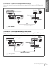
Ceiling
The bottom
surface of the
mount
bracket
Center of the
supporting pole
Center of the lens
Center of the unit
Distance between the ceiling and the surface of
the mount bracket
Using adjustment pipe (b): 150/175/200 mm
(6 / 7 / 7
7
/8 inches)
Using adjustment pipe (c): 250/275/300 mm
(9
7
/8 / 10
7
/8 / 11
7
/8 inches)