


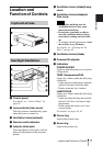
13Location and Function of Controls
Overview
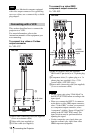
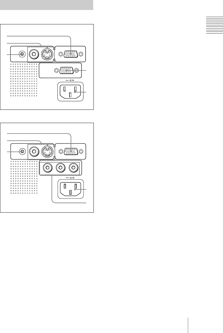
VPL-CS7
VPL-ES2
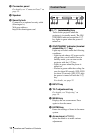
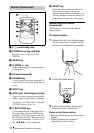
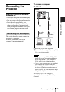
1 INPUT A connector (HD D-sub
15-pin, female)
Connect to external equipment such as a
computer.
Connects to the monitor output on a
computer using the supplied cable.
When inputting a component or 15k
RGB signal, use an optional cable.
For details, see “To connect to a video
GBR/component output connector” on
page 18.
2 Video input connector
Connect to external video equipment
such as a VCR.
• VIDEO (phono type): Connects to
the composite video output of video
equipment.
• S VIDEO (mini DIN 4-pin):
Connects to the S video output (Y/C
video output) of video equipment.
3 AUDIO (stereo minijack)
connector
When listening to sound output from the
computer, connect to the audio output of
the computer.
When listening to sound output from the
VCR, connect to the audio output of the
VCR.
4 Monitor output connector (VPL-
CS7 only)
Connects to the monitor input on a
monitor. Outputs the signal from a
computer connected to INPUT A.
5 AC IN socket
Connects the supplied AC power cord.
6 Component input connector (for
VPL-ES2 only)
According to the connected equipment,
component (Y/C
B/CR), HDTV or DTV
(Y/PB/PR) signal is selected.
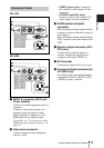
Connector Panel
INPUT A
S VIDEO
VIDEOAUDIO
MONITOR OUT
1
2
3
4
5
INPUT A
S VIDEO
VIDEOAUDIO
YP
B
/C
B
P
R
/C
R
1
2
3
5
6