Getting Started
Location and Function of Parts and Controls
6
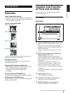
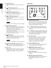
F RECEIVING lamp
Lights when the printer receives print data from a
PC.
G CUT button (page 22, 33)
Press to cut the completed print using the internal
paper cutter.
H FEED button (page 10, 22, 33)
Hold down to feed paper. While a print job is in
progress, press to cancel the print job.
I CAPTURE button (page 23)
In the multi-picture mode, press to store the print
image in memory.
This function is not available in the single-picture
mode.
Note
This function is available only in the analog mode.
J COPY button (page 24)
In the multi-picture mode, use this button to print
images stored in memory (with the CAPTURE
button) side by side on a single sheet.
In the single-picture mode, press to print another
copy of the last printed image.
In either mode, press once to print only the number
of prints set in the “QTY” menu.
K PRINT button
Prints the image currently displayed on the video
monitor. The image displayed when you press the
PRINT button is stored in memory.
Note
This function is available only in the analog mode.
L OPEN/CLOSE button (page 10, 22, 33)
Press to open or close the paper door. While a print
job is in progress, press to cancel the print job.
M Paper door
Open to install and replace printing paper, and to
clean the head and platen roller. Use the OPEN/
CLOSE button to open or close the paper door.
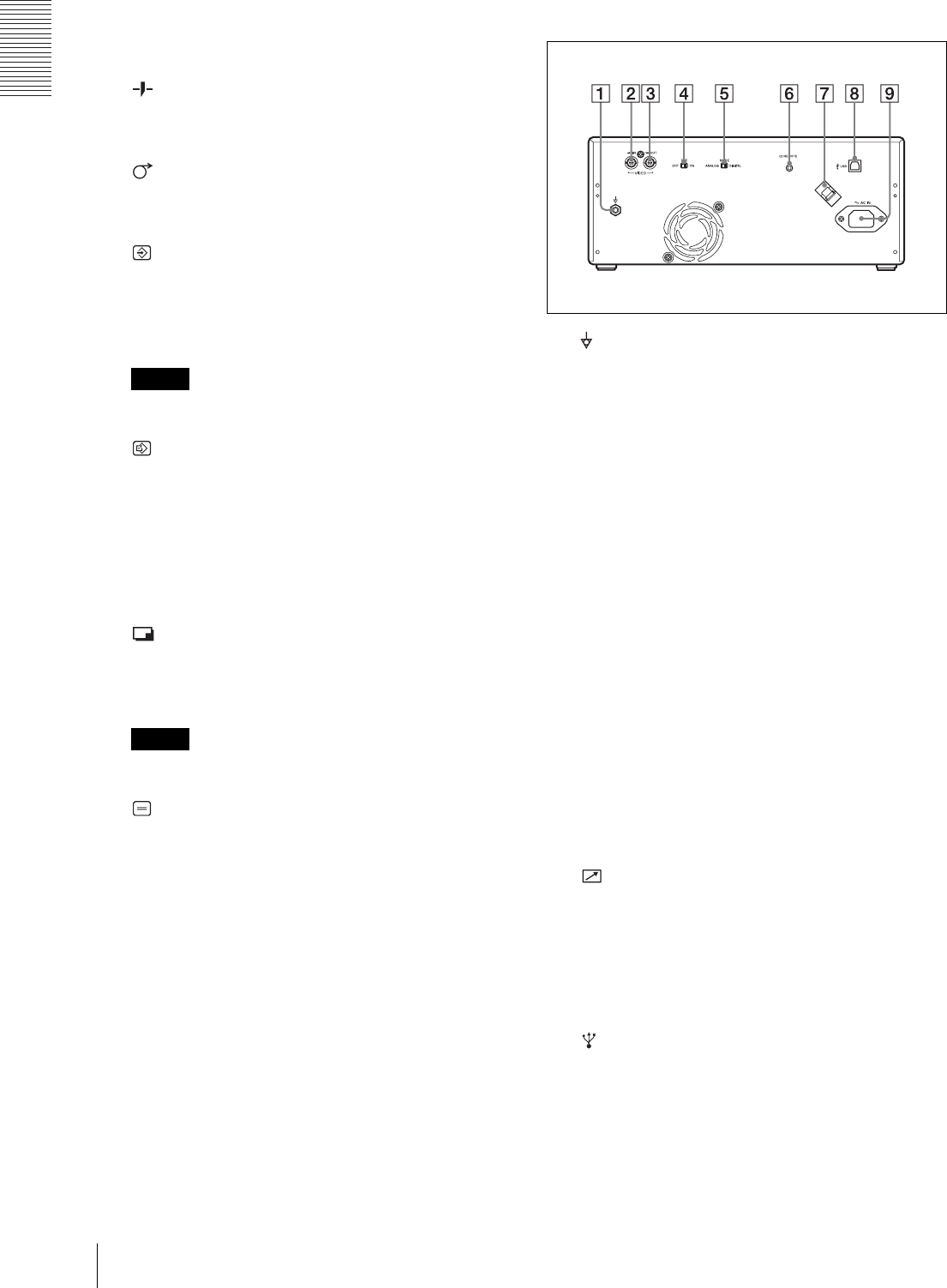
Rear Panel
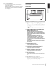
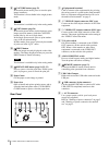
A Equipotential terminal
Used to connect to the equipotential plug to bring
the various parts of a system to the same potential.
Refer to “Important safeguards/notices for use in
the medical environments” on page 2.
B t VIDEO IN (input) connector (BNC type)
Connect to the video output connector of the video
equipment.
C T VIDEO OUT (output) connector (BNC type)
Connect to the video input connector of the video
monitor. The output signal depends on the setting of
the “VIDEO” item of the menu.
D 75 Ω select switch
ON: When nothing is connected to the VIDEO
OUT connector, set the switch to this position.
OFF: When a video monitor or other video
equipment is connected to the VIDEO OUT
connector, set the switch to this position.
E ANALOG/DIGITAL switch
Press to switch between analog and digital modes.
Turn the printer off before switching.
F REMOTE connector (page 12)
Connects the RM-91 remote control unit for
controlling print operation from a distance.
G USB Cable Clamper
Holds and secures the USB cable connected to the
USB port.
H USB connector (4-pin connector)
Use the supplied USB cable to connect a PC with a
USB (USB 2.0 compliant) interface to this
connector.


