SSI
ERP2U Power Supply Design Guide, V2.31
- 18 -
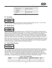
1 SMBus Clock White/Green Stripe
2 SMBus Data White/Yellow Stripe
3 SMBAlert
4 ReturnS Black/White Stripe
5 3.3RS Orange/White Stripe
6.2 Grounding
STATUS
Required
The ground of the pins of the power assembly wire harness provides the power return path. The wire harness
ground pins shall be connected to safety ground (power supply enclosure).
6.3 Remote Sense
STATUS
Optional
The power assembly may have remote sense for the +3.3V (3.3VS) and return (ReturnS) if the Optional Server
Signal connector is implemented and the module has a +3.3V output. The remote sense return (ReturnS) is used
to regulate out ground drops for all output voltages. The +3.3V remote sense (3.3VS) is used to regulate out
drops in the system for the +3.3 V output. The remote sense input impedance to the power sub-assembly must
be greater than 200 ohms on 3.3 VS and ReturnS. This is the value of the resistor connecting the remote sense
to the output voltage internal to the power assembly. Remote sense must be able to regulate out a minimum of
200 mV drop on the +3.3 V output. The remote sense return (ReturnS) must be able to regulate out a minimum of
200 mV drop in the power ground return. The current in any remote sense line shall be less than 5 mA to prevent
voltage sensing errors. The power supply must operate within specification over the full range of voltage drops
from the power assembly’s output connector to the remote sense points.
6.4 Output Power/Currents
STATUS
Recommended
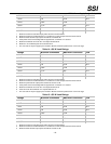
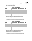
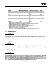
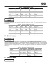
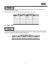
The following tables define the power and current ratings for different recommended power levels. Depending
upon the system design, the power supply modules may have less outputs than required by the system (example:
+12V and 5VSB). If there are less outputs than required by the system on the module, the cage shall have
additional DC/DC converters to generate the voltages not produced by the modules (example: +12V/+5V,
+12V/+3.3V, +12V/-12V). The combined output power of all outputs from the cage shall not exceed the rated
output power. The power assembly shall meet both static and dynamic voltage regulation requirements over the
full load ranges. The power sub-assembly shall supply redundant power over the full load ranges.
Table 13: 550 W Load Ratings
Voltage Minimum Continuous Maximum Continuous Peak
+3.3 V
7
0.8 A 24 A
+5 V
7
0.5 A 24 A


