SSI
ERP2U Power Supply Design Guide, V2.31
- 21 -
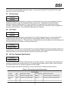
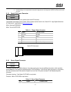
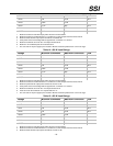
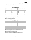
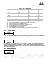
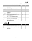
Table 18: 800 W Load Ratings
Voltage Minimum Continuous Maximum Continuous Peak
+3.3 V
7
0.8 A 24 A
+5 V
7
0.5 A 30 A
+12V1 0 A 16 A 18 A
+12V2 0 A 16 A 18 A
+12V3 0.9 A 16 A 18 A
+12V4 0.1 A 16 A 18 A
-12 V 0 A 0.5 A
+5 VSB 0.1 A 3.0 A 3.5 A
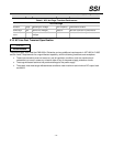
1. Maximum continuous total DC output power should not exceed 800 W.
2. Maximum continuous combined load on +3.3 VDC and +5 VDC outputs shall not exceed 170 W.
3. Maximum Peak total DC output power should not exceed 880 W.
4. Peak power and current loading shall be supported for a minimum of 10 second.
5. Maximum combined current for the 12 V outputs shall be 64 A.
6. Maximum 12V combined peak current shall be 70 A.
7. The 3.3V and 5V may be supply by the module or DC/DC converters powered from +12V in the cage.
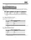
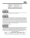
6.4.1 Standby Outputs
STATUS
Required
The 5 VSB output shall be present when an AC input greater than the power supply turn on voltage is applied.
6.4.2 Fan operation in standby mode
STATUS
Required
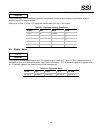
For standby output at the higher power level, when the supply is in standby mode it is required that the power
supply fan(s) remain running at a very low speed. This helps prevent power supply overheating when many
systems in the same rack are in standby mode. Running the fan(s) in standby mode also allows better cooling to
the standby power converter.
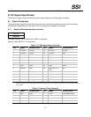
6.5 Voltage Regulation
STATUS
Required
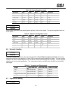
The power assembly output voltages must stay within the following voltage limits when operating at steady state
and dynamic loading conditions. These limits include the peak-peak ripple/noise specified in Section
5.10. All
outputs are measured with reference to the return remote sense (ReturnS) signal. The 5 V, 12V1, 12V2, 12V3,
12V4, –12 V and 5 VSB outputs are measured at the power assembly connectors referenced to ReturnS. The
+3.3 V is measured at its remote sense signal (3.3VS) located at the signal connector.


