


SSI
ERP2U Power Supply Design Guide, V2.31
- 33 -
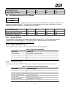
FRU File ID {Not required}
PAD Bytes {Added as necessary to allow for 8-byte offset to next area}
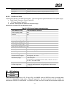
8.5.2.2 MultiRecord Area
Implement as defined by the IPMI FRU document. The following record types shall be used on this power supply:
• Power Supply Information (Record Type 0x00)
• DC Output (Record Type 0x01)
• No other record types are required for the power supply.
MultiRecord information shall be defined as follows:
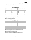
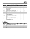
Table 33: FRU Device Product Information Area
Field Name (PS Info) Field Information Definition
Overall Capacity (watts) 480
Peak VA 550
Inrush current (A) 50
Inrush interval (ms) 5
Low end input voltage range 1 90
High end input voltage range 1 140
Low end input voltage range 2 180
High end input voltage range 2 264
A/C dropout tol. (ms) 20
Binary flags Set for: Hot Swap support, Autoswitch, and PFC
Peak Wattage
Set for: 10 s, 550 W
Combined wattage Set for 5 V & 3.3V combined wattage of 115 W
Predictive fail tach support Not supported, 00h value
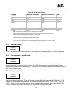
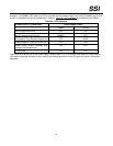
Field Name (Output) Field Description:
Five outputs are to be defined from #1 to #5, as follows: +3.3 V, +5
V, +12 V, -12V, and +5 VSB.
Output Information Set for: Standby on +5 VSB, No Standby on all others.
All other output fields Format per IPMI specification, using parameters in the EPS12V
specification.
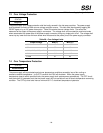
8.6 LED Indicators
STATUS
Required
There shall be a single bi-color LED OR two LEDs, one AMBER and one GREEN, on each hot swap power
module to indicate power supply status. When AC is applied to the power supply and standby voltages are
available the GREEN LED shall BLINK. The GREEN LED shall turn ON to indicate that all the power outputs are