High Performance Two Port 10/100 Managed Ethernet Switch with 32-Bit Non-PCI CPU Interface
Datasheet
SMSC LAN9312 33 Revision 1.4 (08-19-08)
DATASHEET
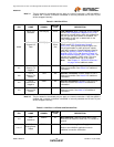
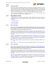
Note: For more information on configuration straps, refer to Section 4.2.4, "Configuration Straps," on
page 40. Additional strap pins, which share functionality with the EEPROM pins, are described
in Table 3.5.
Note 3.6 Configuration strap values are latched on power-on reset or nRST de-assertion.
Configuration strap pins are identified by an underlined symbol name. Some configuration
straps can be overridden by values from the EEPROM Loader. Refer to Section 4.2.4,
"Configuration Straps," on page 40 for more information.
69
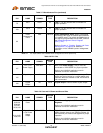
Port 1 Auto-
MDIX Enable
Strap
AUTO_MDIX_1
IS
(PU)
Port 1 Auto-MDIX Enable Strap: Configures the
Auto-MDIX functionality on Port 1. When latched
low, Auto-MDIX is disabled. When latched high,
Auto-MDIX is enabled.
See Note 3.6.
70
Port 2 Auto-
MDIX Enable
Strap
AUTO_MDIX_2
IS
(PU)
Port 2 Auto-MDIX Enable Strap: Configures the
Auto-MDIX functionality on Port 2. When latched
low, Auto-MDIX is disabled. When latched high,
Auto-MDIX is enabled.
See Note 3.6.
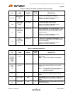
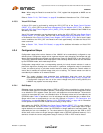
Table 3.7 Miscellaneous Pins
PIN NAME SYMBOL
BUFFER
TYPE DESCRIPTION
77-79,
82
General
Purpose I/O
Data
GPIO[11:8] IS/OD12/
O12
(PU)
Note 3.7
General Purpose I/O Data: These general
purpose signals are fully programmable as either
push-pull outputs, open-drain outputs, or Schmitt-
triggered inputs by writing the General Purpose I/O
Configuration Register (GPIO_CFG) and General
Purpose I/O Data & Direction Register
(GPIO_DATA_DIR). For more information, refer to
Chapter 13, "GPIO/LED Controller," on page 162.
Note: The remaining GPIO[7:0] pins share
functionality with the LED output pins, as
described in Table 3.1 and Table 3.2.
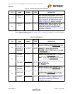
63
Interrupt
Output
IRQ O8/OD8 Interrupt Output: Interrupt request output. The
polarity, source and buffer type of this signal is
programmable via the Interrupt Configuration
Register (IRQ_CFG). For more information, refer to
Chapter 5, "System Interrupts," on page 49.
71
System Reset
Input
nRST IS
(PU)
System Reset Input: This active low signal allows
external hardware to reset the LAN9312. The
LAN9312 also contains an internal power-on reset
circuit. Thus, this signal may be left unconnected if
an external hardware reset is not needed. When
used, this signal must adhere to the reset timing
requirements as detailed in Section 15.5.2, "Reset
and Configuration Strap Timing," on page 444.
Note: The LAN9312 must always be read at
least once after power-up or reset to
ensure that write operations function
properly.
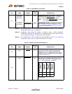
Table 3.6 Dedicated Configuration Strap Pins (continued)
PIN NAME SYMBOL
BUFFER
TYPE DESCRIPTION


