


– 18 –
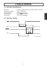
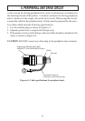
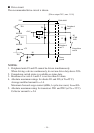
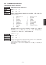
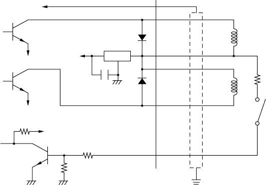
■ Drive circuit
The recommended drive circuit is shown.
NOTES:
1. Peripheral units #1 and #2 cannot be driven simultaneously.
When driving a device continuously, do not use drive duty above 20%.
2. Compulsion switch status is available as status data.
3. Resistance for coils L1 and L2 is not less than 24 ohms.
4. Absolute maximum ratings for diodes D1 and D2 (at Ta=25˚C):
Average rectified current Io = 1A
Maximum forward surge current (60Hz,1-cycle sine wave) I
FSM=40A
5. Absolute maximum rating for transistors TR1 and TR2 (at Ta = 25˚C):
Collector current Ic = 2A
7824
F.G
TR1
M-GND
TR2
M-GND
TR3
+5V
+24V
R1
R2
6
5
4
3
2
1
L1
L2
R3
4.7kΩ
1/4W
Frame
ground
D1
D2
Peripheral
unit 1
With shield
Peripheral
unit 2
Compulsion
switch
[Drive output 24V, max. 1.0 A]