Cabling the System 2-5
2
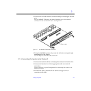
Warning – Risk of electric shock. Do NOT turn on AC power to the unit yet.
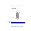
4. Continue with Section 2.4 through Section 2.7 for further cabling
instructions, and then see Section 2.2 to replace the rear screen and kick
panel.
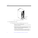
2.3.2 Connecting the Enterprise 4000 System Power Cord
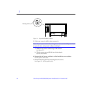
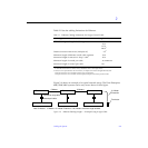
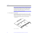
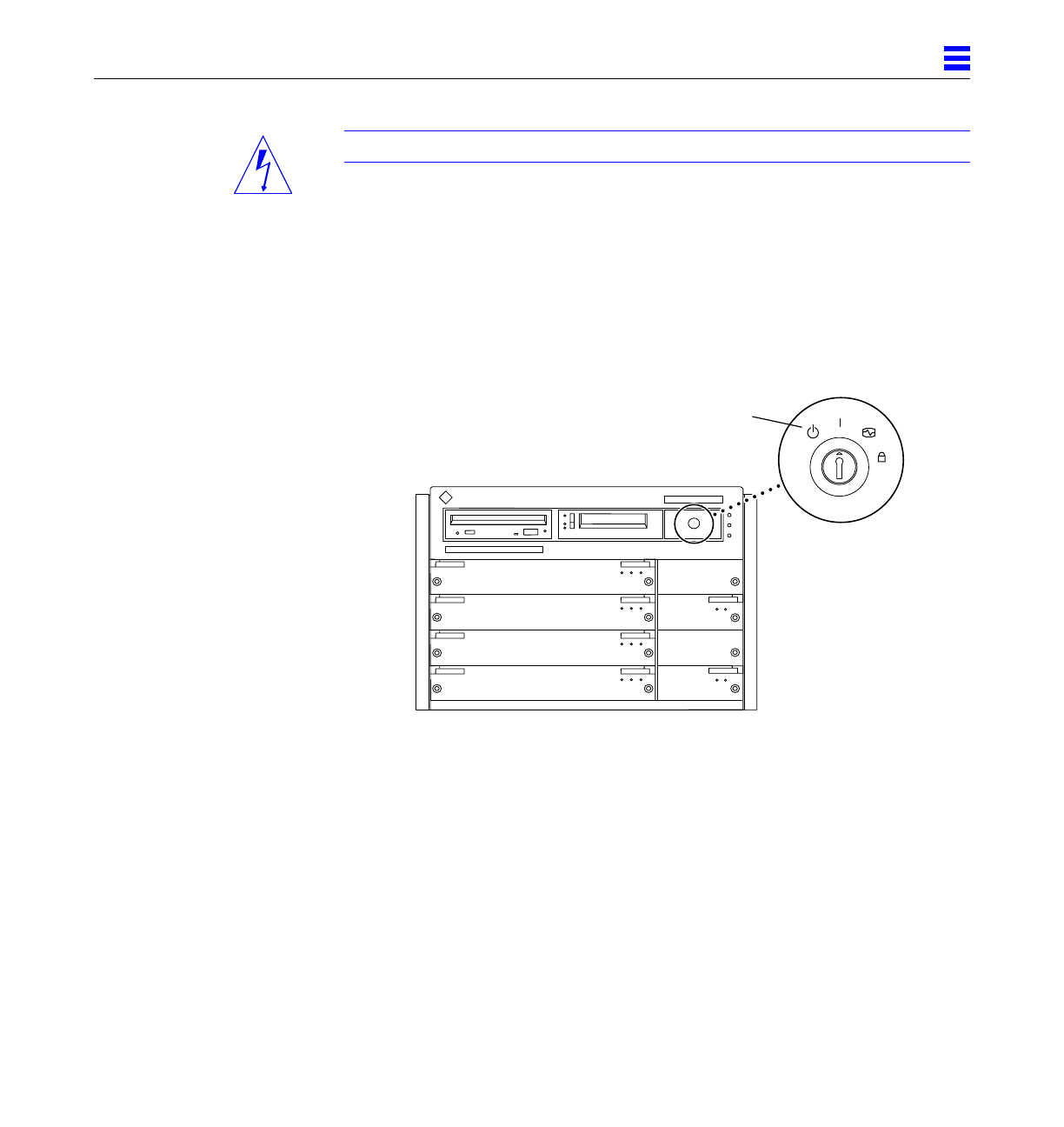
1. Insert the key provided with your system into the front panel key switch.
Turn it to the Standby position (fully counterclockwise).
See Figure 2-4.
Figure 2-4 Key Switch Positions
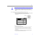
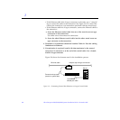
2. Turn the AC power switch to Off.
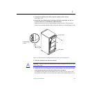
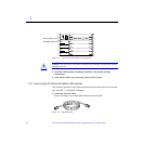
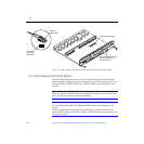
This switch is in the upper left corner of the system rear. See Figure 2-5.
3. Connect the female end of the power cord into the AC connector.
This connector is to the left of the AC power switch on the system rear.
See Figure 2-5.
4. Connect the male end of the power cord into a grounded wall outlet.
The outlet must be a 100-240 VAC 15A circuit.
Standby


