


5-4
SuperWorkstation 7047A-73/7047A-T User's Manual
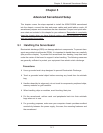
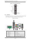
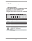
5-4 I/O Ports
The I/O ports are color coded in conformance with the PC 99 specifi cation. See
Figure 5-2 below for the colors and locations of the various I/O ports.
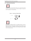
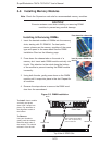
Figure 5-1. Control Panel Header Pins
Figure 5-2. I/O Ports
NMI
x (Key)
Vcc
Vcc
Vcc
Vcc
Vcc
Vcc
Reset (Button)
Power (Button)
Ground
x (Key)
Power On LED
HDD LED
NIC1 LED
NIC2 LED
OH/Fan Fail LED
Power Fail LED
Ground
Ground
2 1
20 19
1. COM1 Port (Turquoise) 9. MIC In
2. USB 2.0 Port 0 10. Line Out
3. USB 2.0 Port 1 11. Line In
4. USB 2.0 Port 2 12. Gb LAN 1 Port
5. USB 2.0 Port 2 13. CGb LAN 2 Port
6. SPDIF Out 14. USB 3.0 Port 0 (or USB keyboard/mouse)
7. Surround Out 15. USB 3.0 Port 1 (or USB keyboard/mouse)
8. CEN/LFE Out 16. PS/2 Keyboard or Mouse
1
10
11
12
13
14
15
16
2
3
4
5
6
7
8
9