


5-24
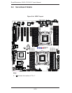
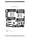
SuperWorkstation 7047A-73/7047A-T User's Manual
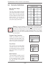
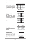
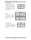
SGPIO Header
Two SGPIO (Serial General Purpose
Input/Output) headers are designated
T-SGPIO1 and SGPIO2. These head-
ers are used to communicate with
the system's enclosure management
chip. See the table on the right for pin
defi nitions.
SGPIO Header
Pin Defi nitions
Pin# Defi nition Pin Defi nition
1NC 2 NC
3 Ground 4 Data
5 Load 6 Ground
7 Clock 8 NC
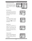
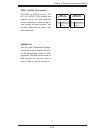
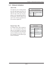
IEEE 1394a_1/ 1394a_2
Connectors
1394a_1 (CNF1) and 1394a_2 (CNF2)
provide the IEEE 1394a (Firewire)
connections on the serverboard.
Connect IEEE 1394 cables to the
connectors for IEEE 1394a support.
See the tables on the right for pin
defi nitions.
1394_1
Pin Defi nitions
Pin# Defi nition Pin# Defi nition
1 PTPA0+ 2 PTPA0-
3 GND 4 GND
5 PTPB0+ 6 PTPB0-
7 PWR 1394a 8 PWR 1394a
10 Shield GND
1394_2
Pin Defi nitions
Pin#
Defi nition
Pin#
Defi nition
1 PTPA1+ 2 PTPA1-
3 GND 4 GND
5 PTPB1+ 6 PTPB1-
7 PWR 1394a 8 PWR 1394a
10
Shield GND
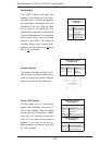
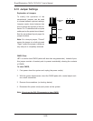
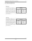
DOM Power Connector
A power connector for SATA DOM
(Disk On Module) devices is located
at JSD1. Connect an appropriate cable
here to provide power support for your
DOM devices.
DOM PWR
Pin Defi nitions
Pin# Defi nition
1 +5V
2 Ground
3 Ground
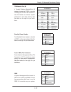
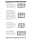
JRK1/JRK2
The JRK1 header allows the Option
ROM to upgrade the onboard chipset.
JRK2 is a RAIDKey used to provide
RAID support for system performance
enhancement.
JRK1
Pin Defi nitions
Pin# Defi nition
1 Ground
2 Signal
3 Ground
JRK2
Pin Defi nitions
Pin# Defi nition
1 Ground
2 Signal
3 Ground
NC = No Connection